Oil well gas injection method

A technology for oil wells and gas injection, which is applied in earthwork drilling, wellbore/well components, production fluids, etc. It can solve the problems of inability to achieve accurate calculation of formation pressure, prediction error of pure gas injection pressure at the wellhead, and inability to meet the requirements of pure nitrogen injection in Tahe River. Wellhead pressure requirements and other issues

Inactive Publication Date: 2017-08-18
CHINA PETROLEUM & CHEM CORP
View PDF6 Cites 2 Cited by
  • Summary
  • Abstract
  • Description
  • Claims
  • Application Information

AI Technical Summary

Problems solved by technology

[0005] 1. The pressure of pure nitrogen injection in Tahe ultra-deep well is as high as 55MPa. At present, the highest pressure level of domestic reciprocating nitrogen injection compressor is 50MPa, which cannot meet the wellhead pressure requirements of pure nitrogen injection in Tahe;
[0006] 2. Nitrogen injection wells in Tahe are mostly old wells, and 9 5 / 8"casing tie-back mode, the pressure of the casing head is 34.5MPa, the pressure is low, and there is a risk of gas injection safety;
[0007] 3. The pressure measurement data in previous years cannot realize the accurate calculation of the current formation pressure, which leads to errors in the prediction of the pure gas injection pressure at the wellhead;
[0008] 4. The gas injection technology in foreign oilfields uses carbon dioxide and natural gas as the main gas source. Domestic nitrogen injection technology is mainly carried out in sandstone shallow reservoirs, and the gas-water injection is the main method. There is no mature experience for reference
[0009] At the same time, considering that the nitrogen injection technology for ultra-deep and high-pressure oil wells does not have a mature wellhead pressure reduction technology, it is urgent to establish a set of pressure-reducing nitrogen injection methods

Method used


Image

  • Oil well gas injection method
  • Oil well gas injection method
  • Oil well gas injection method

Examples


Embodiment Construction

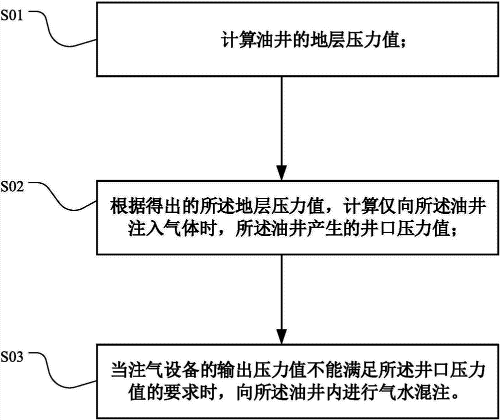
[0042] Embodiments of the technical solutions of the present invention will be described in detail below in conjunction with the accompanying drawings. The following examples are only used to illustrate the technical solutions of the present invention more clearly, and therefore are only examples, rather than limiting the protection scope of the present invention.

[0043] like figure 1 As shown, the present invention provides a gas injection method for oil wells. The gas injection method for oil wells determines the working conditions and chooses to use existing gas injection equipment to inject gas into the oil well or perform gas-water mixed injection into the oil well. The gas injection method is suitable for ultra-deep oil wells, especially for the calculation of gas injection pressure and gas-water mixed injection ratio of oil wells where the formation pressure is high and the existing gas injection equipment cannot realize pure gas injection. In this embodiment, the ga...


PUM


Abstract

The invention discloses an oil well gas injection method. The oil well gas injection method comprises the steps that (1) the stratum pressure value of an oil well is calculated; (2) according to the obtained stratum pressure value, the well mouth pressure value generated by the oil well when only gas is injected into the oil well is calculated; and (3) when the output pressure value of gas injection equipment cannot meet the requirement of the well mouth pressure value, gas and water are injected into the oil well in a mixed mode. Through the oil well gas injection method, the well mouth gas injection pressure is effectively lowered, the gas-water mixing injection ratio adopted by a gas injection well under the condition of existing gas injection equipment is accurately predicted, technological support is provided for the gas injection technology, important guarantee is provided for development of the oil field gas injection three-time oil extraction technology, and application and promotion, under the condition of the existing gas injection equipment, of the technology that the nitrogen gas is injected to improve the recovery ratio are achieved.

Description

technical field [0001] The invention relates to the technical field of oil and gas exploitation, in particular to an oil well gas injection method. Background technique [0002] At present, the exploitation of Tahe oilfields has entered the late stage of high water cut. Although a series of engineering technical measures such as profile control and water plugging have been taken, some crude oil remains underground and cannot be recovered, especially in low-permeability reservoirs, heavy oil reservoirs, etc. Both oil and gas condensate reservoirs have not been fully and rationally developed, and gas injection has become a rapidly developing enhanced oil recovery technology. [0003] Tahe fractured-vuggy carbonate reservoirs are dominated by large fractures and caves, and the reservoir has the characteristics of "two ultras and three highs", that is, ultra-deep, ultra-thick, high temperature, high salinity, and high sulfide content Hydrogen, the production declines and the wa...

Claims


Application Information

Patent Timeline
Patent Type & Authority Applications(China)
IPC IPC(8): E21B43/16
CPCE21B43/168
Inventor 李婷婷王雷吴文明曾文广张建军马清杰王建海甄恩龙杨利萍任向海劳胜华焦保雷冯一波
Owner CHINA PETROLEUM & CHEM CORP
Why Eureka
Try Eureka