Single crank unit of light crankshaft of internal combustion engine
A light-weight, internal combustion engine technology, applied in the direction of crankshaft, engine components, engine lubrication, etc., can solve the problems of weak overall coordination, poor lubrication effect, and low weight reduction, and achieve strong overall coordination, reduced mass, and light weight Highly Quantitative Effects
- Summary
- Abstract
- Description
- Claims
- Application Information
AI Technical Summary
Problems solved by technology
Method used
Image
Examples
Embodiment 1
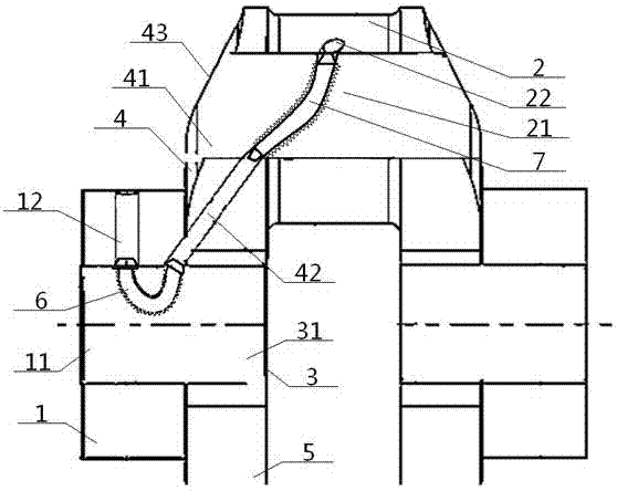
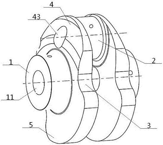
[0049] see Figure 1 to Figure 4 , a single throw unit of a lightweight crankshaft for an internal combustion engine, comprising a main journal 1, a connecting rod journal 2 and a crank block 3, the main journal 1 is connected to the middle of the crank block 3, and the crank block 3 is located on the crank block 3, the main shaft The upper and lower ends of the junction of the neck 1 are respectively the crank arm 4 and the balance weight 5, the crank arm 4 is connected to the connecting rod journal 2, and the main journal 1 and the connecting rod journal 2 are respectively located on both sides of the crank block 3;
[0050] The inside of the main journal 1 is provided with a No. 1 through hole 11 , the inside of the part where the crankshaft block 3 meets the main journal 1 is provided with a No. 2 through hole 31 , and the inside of the crank arm 4 is provided with a No. 3 through hole. Through hole 41, the inside of connecting rod neck 2 is provided with through hole No. ...
Embodiment 2
[0052] Basic content is the same as embodiment 1, the difference is:
[0053] The No. 1 through hole 11 and the No. 2 through hole 31 are coaxially arranged and have the same diameter; the right part of the No. 3 through hole 41 is flush with the No. 4 through hole 21, and the left part of the No. The outer surface of the crank arm 4 joins to form an outer through hole 43, the diameter of which is smaller than the diameter of the right part of No. 3 through hole 41 (the axis of the through hole can be coaxial with the axis of the corresponding connecting pin, or there must be offset). The diameter of the No. 1 through hole 11 is 25%-75% of the diameter of the main journal 1, and the diameter of the No. 4 through hole 21 is 25%-75% of the diameter of the connecting rod neck 2 (below this range, the effect is not obvious , above this range reduces the size of the overlapping region, weakening strength and stiffness).
Embodiment 3
[0055] Basic content is the same as embodiment 1, the difference is:
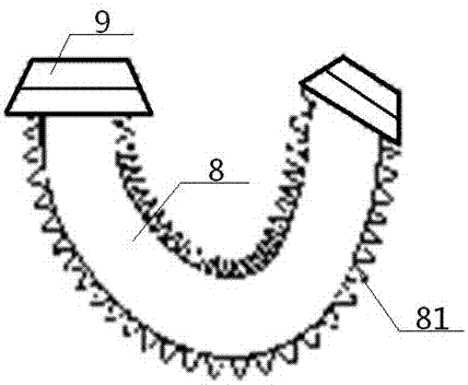
[0056] The main journal oil passage 12 communicates with one end of the crank arm oil passage 42 through the No. 1 built-in oil pipe 6, and the other end of the crank arm oil passage 42 communicates with the connecting rod neck oil passage 22 through the No. 2 built-in oil pipe 7. The oil pipe 6 is located in the first through hole 11 and the second through hole 31 , and the second built-in oil pipe 7 is located in the third through hole 41 and the fourth through hole 21 . The No. 1 built-in oil pipe 6 and the No. 2 built-in oil pipe 7 have the same structure, both including the oil pipe body 8 and the wedge-shaped joint 9 connected to its two ends; the wedge-shaped joint 9 is a trapezoidal structure, and the large-diameter bottom surface of the wedge-shaped joint 9 and The oil pipe body 8 communicates, the small-diameter top surface of the wedge joint 9 communicates with the main journal oil passage 12, th...
PUM
 Abstract
Description
Claims
Application Information
 - R&D
- Intellectual Property
- Life Sciences
- Materials
- Tech Scout
- Unparalleled Data Quality
- Higher Quality Content
- 60% Fewer Hallucinations
Browse by: Latest US Patents, China's latest patents, Technical Efficacy Thesaurus, Application Domain, Technology Topic, Popular Technical Reports.
© 2025 PatSnap. All rights reserved.Legal|Privacy policy|Modern Slavery Act Transparency Statement|Sitemap|About US| Contact US: help@patsnap.com


