Micro valve system and method for generating and controlling parking air bubbles

A control method and air bubble technology, applied in chemical instruments and methods, valve devices, laboratory containers, etc., can solve problems such as troublesome operation, complicated processing, and cumbersome structure, and achieve the effect of simple design

Active Publication Date: 2017-08-18
HEBEI UNIV OF TECH
View PDF8 Cites 2 Cited by
  • Summary
  • Abstract
  • Description
  • Claims
  • Application Information

AI Technical Summary

Problems solved by technology

These valves have cumbersome structure, complex processing, or troublesome operation, which is not conducive to large-scale integration.

Method used


Image

  • Micro valve system and method for generating and controlling parking air bubbles
  • Micro valve system and method for generating and controlling parking air bubbles
  • Micro valve system and method for generating and controlling parking air bubbles

Examples


Embodiment 1

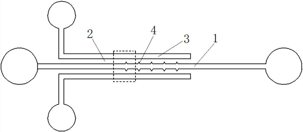
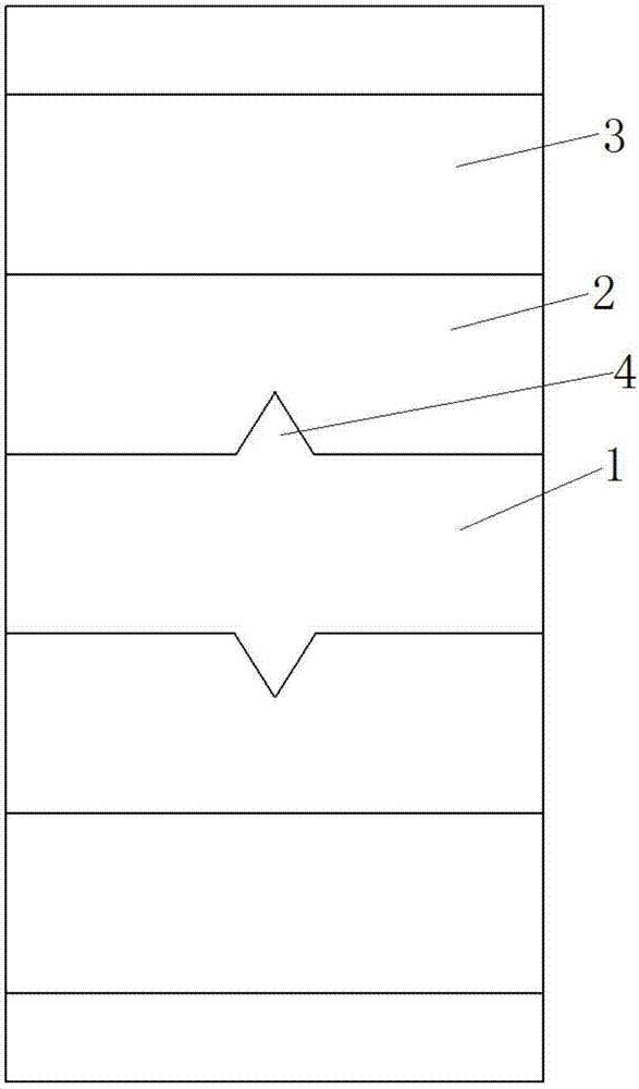
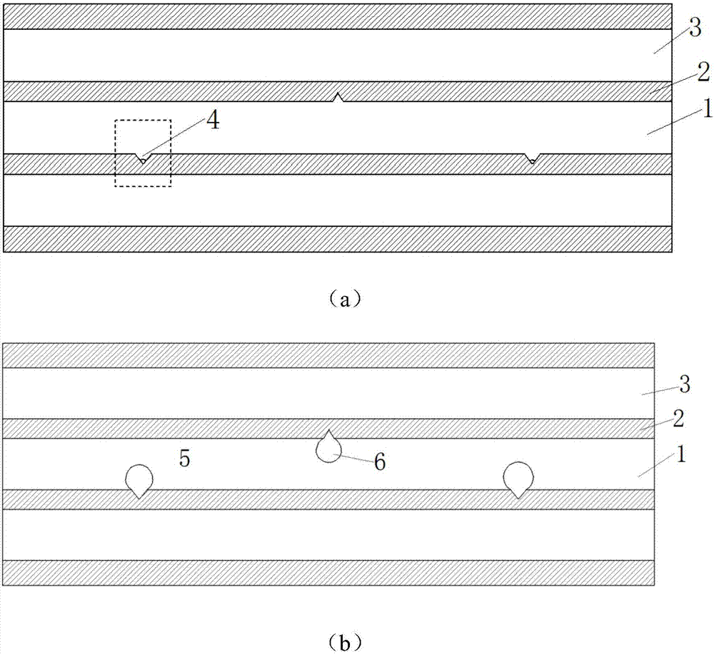
[0031]A micro-channel for generating and controlling parking bubbles, comprising a liquid flow channel 1, a water-repellent gas-permeable layer 2, an air pressure control channel 3 and at least one parking bubble generation chamber 4; the air pressure control channel 3 is maintained with the liquid flow channel 1 A certain distance is distributed in parallel and is not connected; the water-repellent and air-permeable layer 2 is located between the air pressure control flow channel 3 and the microfluidic channel 1, and the material is polydimethylsiloxane (PDMS); the inner wall of the liquid flow channel 1 At least one parking bubble generating cavity 4 is provided; the parking bubble generating cavity 4 is an indented triangular prism structure opened on the inner wall of the liquid flow channel 1; the cross section of the parking bubble generating cavity 4 is an isosceles triangle; The vertex angle of the cross-section of the parking bubble generation chamber 4 is smaller than...

Embodiment 2

[0036] A micro-channel for generating and controlling parking bubbles, comprising a liquid flow channel 1, a water-repellent gas-permeable layer 2, an air pressure control channel 3 and at least one parking bubble generation chamber 4; the air pressure control channel 3 is maintained with the liquid flow channel 1 A certain distance is distributed in parallel and is not connected; the water-repellent and air-permeable layer 2 is located between the air pressure control flow channel 3 and the microfluidic channel 1, and the material is polydimethylsiloxane (PDMS); the inner wall of the liquid flow channel 1 At least one parking bubble generation chamber 4 is provided; the parking bubble generation chamber 4 is an inset triangular prism structure opened on the inner wall of the liquid flow channel 1; the cross section of the parking bubble generation chamber 4 is a right triangle; The vertex angle of the cross-section of the bubble generation chamber 4 is smaller than the forward...


PUM


Abstract

The invention discloses a micro valve system and method for generating and controlling parking air bubbles. The micro valve system comprises a liquid runner, a water repelling gas-permeable layer, an air pressure control channel and at least one parking air bubble generating cavity, wherein the air pressure control channel and the liquid runner are distributed in parallel and do not communicate with each other; the water repelling gas-permeable layer is located between the air pressure control channel and a micro fluid channel; the inner wall, on one side of the liquid runner, of the water repelling gas-permeable layer is provided with the parking air bubble generating cavities which are of concave structures formed in the inner walls of the water repelling gas-permeable layer; and the apex angles of the cross sections of the parking air bubble generating cavities are smaller than the flowing advancing contact corners of liquid in the liquid runner. According to the method, the parking air bubbles generated in a micro runner serve as a micro valve of a micro flow control chip, the gas pressure intensity in the channels is controlled by controlling the air pressure, then the shape and dimension of the parking air bubbles are controlled, and circulation or blocking of the liquid runner is achieved.

Description

technical field [0001] The invention relates to the field of microfluidic chips, in particular to a microvalve system for generating and controlling parking bubbles and a method for generating and controlling them. Background technique [0002] Microfluidic technology or microfluidics (Microfluidics) is a scientific and technological system that operates and processes microfluids at the micron scale, and is derived from Micro Electro-Mechanical Systems (MEMS, Micro Electro-Mechanical System). Using microfluidic technology, modules such as pretreatment, reaction, and detection can be integrated on a micron-scale chip, and biological and chemical samples can be quickly and efficiently reacted and processed. It has become a comprehensive biochemistry, life science, precision manufacturing Emerging interdisciplinary subjects in the fields of materials science, fluid mechanics, etc. The microfluidic system has the characteristics of high heat and mass transfer efficiency and low...

Claims


Application Information

Patent Timeline
Patent Type & Authority Applications(China)
IPC IPC(8): F16K99/00B01L3/00
Inventor 刘吉晓周一笛李博文杨若曦李铁军
Owner HEBEI UNIV OF TECH
Why Eureka
Try Eureka