
Regenerative heat exchanger with improved sealing frame

A heat exchanger, regenerative technology, applied in heat exchanger sealing devices, heat exchange equipment, regenerative heat exchangers, etc., can solve problems such as unprovided solutions, achieve calculation work and readjustment reduction, reduction The effect of work and manufacturing costs

Inactive Publication Date: 2017-08-18
BALCKE DURR AG
View PDF8 Cites 1 Cited by
  • Summary
  • Abstract
  • Description
  • Claims
  • Application Information

AI Technical Summary

Problems solved by technology

[0007] However, from the list of respective disadvantages, it is clear that the previously used methods do not provide an optimal solution, so that in each case further improvements to the sealing frame remain possible

Method used


Image

  • Regenerative heat exchanger with improved sealing frame
  • Regenerative heat exchanger with improved sealing frame
  • Regenerative heat exchanger with improved sealing frame

Examples


Embodiment Construction

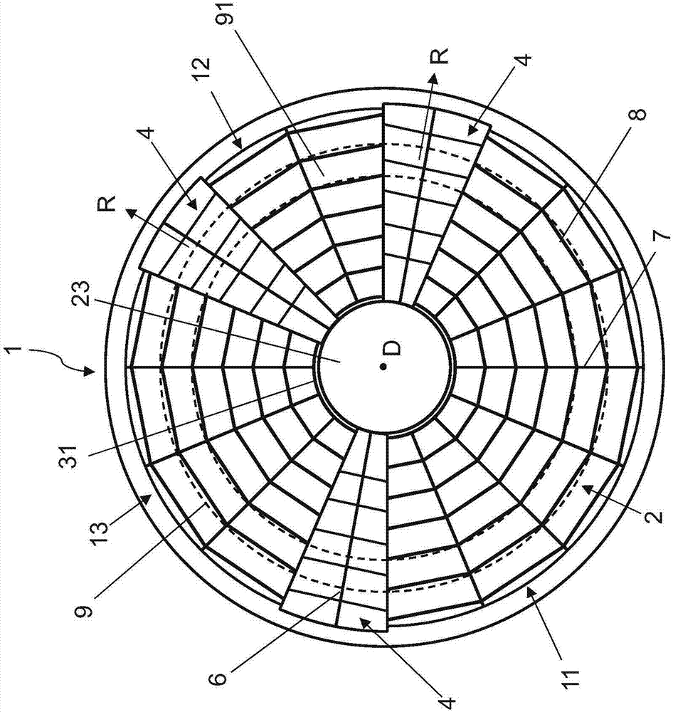
[0030] image 3 A top view along the axial direction D of the heat exchanger 1 according to the invention is shown. The heat accumulator configured as a rotor 2 is surrounded by a stationary housing 3 , is mounted rotatably about an axis of rotation D and is constructed essentially as is known from the prior art. The thermal storage elements 8 are arranged in concentric rings 9 around the rotor core 23 . These rings 9 are subdivided by radial walls 7 extending outwards from the rotor core. The multiple gas volume flows of different temperature flows through the heat exchanger 1 are substantially parallel to the axis of rotation D, but in opposite directions. These gas volume flows can be, for example, a hot flue gas flow and one or more cold combustion air flows. Accordingly, in the example shown, the heat exchanger 1 comprises one flue gas sector 11 and two air sectors 12 , 13 . A direct exchange of gas between the individual cells 91 and thus also between the flue gas sec...


PUM


Abstract

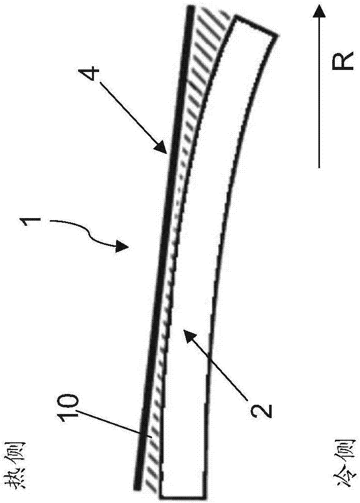
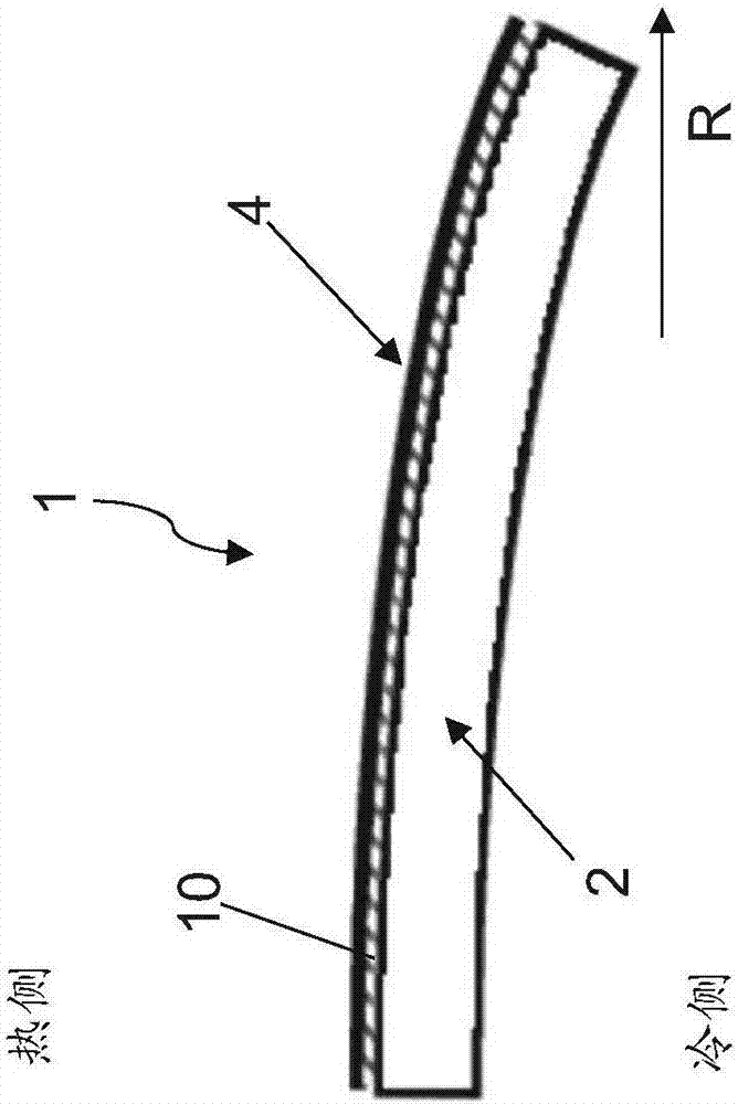
The invention relates to a regenerative heat exchanger (1) with a heat accumulator configured as a rotor (2) which is rotatably mounted about a central axis of rotation (A), a stationary housing (3) surrounding the rotor (2) and sealing means for the rotor (2) ), comprising at least one sealing frame (4) which extends in the radial direction of the rotor (2) and widens towards an outer side of the rotor (2) and has a stiffening device (6), in particular between a smokegasse actuator (11) and an air separator (12 , 13), and an adjusting system (5) for adjusting a distance between the sealing frame (4) and the rotor (2). The stiffening device (6) is designed in such a way that the surface moment of inertia of the sealing frame (4) is substantially constant in its radial direction (R).

Description

technical field [0001] The invention relates to a regenerative heat exchanger according to the preamble of claim 1 . Background technique [0002] Regenerative heat exchangers, such as regenerative air preheaters, are used in various types of steam power plants to use the residual thermal energy of the flue gas leaving the boiler to heat the combustion air supplied to the boiler, thereby increasing power generation plant efficiency. In this regard, preferably, according to Junker In principle, the flue gas flow and at least one gas flow or combustion gas flow are directed in opposite directions within a static housing through a rotating intermediate storage block of substantially cylindrical shape. A rotating intermediate storage block, also known as a rotor, transfers thermal energy from the flue gas sector to at least one air sector. [0003] In addition to the heat capacity of the regenerative heat exchanger, the occurrence of leakage of combustion air into the flue g...

Claims


Application Information

Patent Timeline
Patent Type & Authority Applications(China)
IPC IPC(8): F28D17/00F28F11/00
CPCF28D17/00F28F11/00F28D19/047F28F27/006Y02E60/14F28D20/0056F28D21/001F28F2230/00
Inventor 雷蒙德·克伦泽尔阿明·基尔舍
Owner BALCKE DURR AG
Learn More