Method for testing sensing optical cable-soil deformation coordination

A technology for sensing optical cable and soil deformation, which is applied in the direction of optical instrument testing, machine/structural component testing, measuring devices, etc. It can solve the problems of inconsistency between optical cable and soil deformation, improve accuracy, test equipment is simple, and the principle simple effect

Active Publication Date: 2017-08-18
NANJING UNIV
View PDF4 Cites 7 Cited by
  • Summary
  • Abstract
  • Description
  • Claims
  • Application Information

AI Technical Summary

Problems solved by technology

When the optical cable is pasted or embedded in the geological body, especially when the direct burial method is used to monitor the deformation of the soil, due to the significant difference between the elastic modulus of the optical cable and the soil, the deformation of the optical cable and the soil may be inconsistent.

Method used


Image

  • Method for testing sensing optical cable-soil deformation coordination
  • Method for testing sensing optical cable-soil deformation coordination
  • Method for testing sensing optical cable-soil deformation coordination

Examples


Embodiment Construction

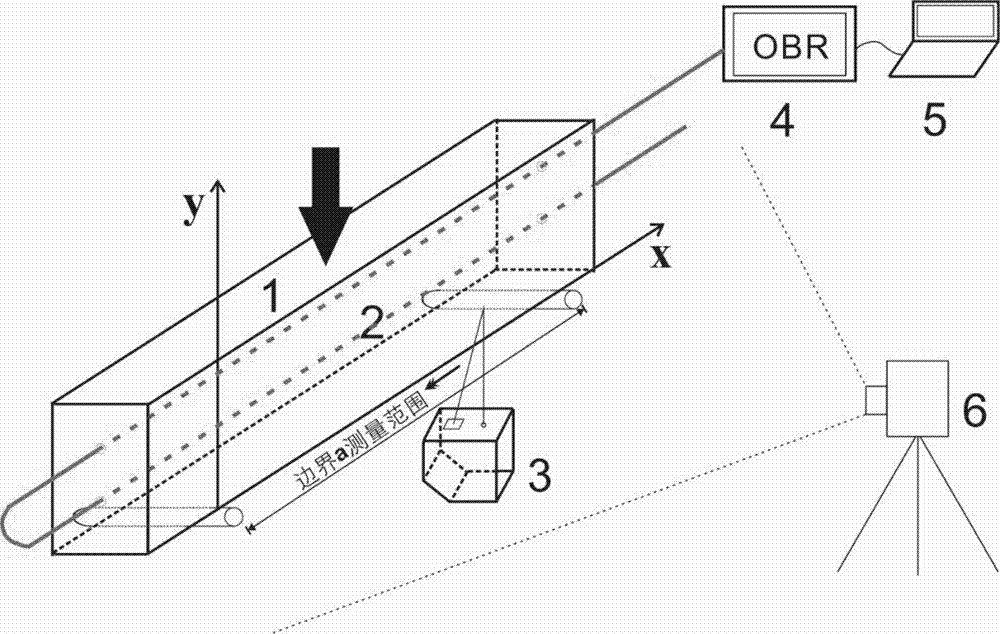
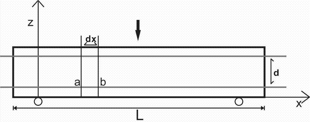
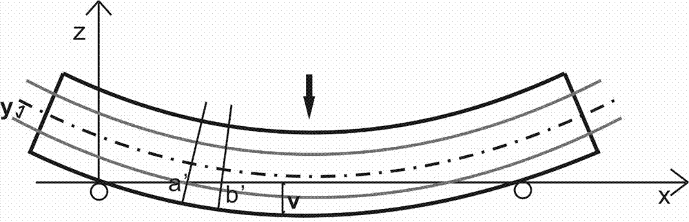
[0038] A method for testing the coordination between the sensing optical cable and soil deformation proposed by the present invention will be described in detail below in conjunction with the accompanying drawings. In the description of the present invention, it should be understood that the orientation or positional relationship indicated by the terms "left", "right", "upper", "lower", "bottom" etc. is based on the orientation or positional relationship shown in the drawings The positional relationship is only for the convenience of describing the present invention and simplifying the description, and does not indicate or imply that the referred device or element must have a specific orientation, be constructed and operated in a specific orientation, "first", "second", etc. It does not indicate the importance of components, so it should not be construed as limiting the present invention. The specific dimensions used in this embodiment are only for illustrating the technical s...


PUM


Abstract

The invention discloses a method for testing sensing optical cable-soil deformation coordination. The method includes the following steps that: a test soil strip is prepared, and a sensing optical cable is embedded in the soil strip; the soil strip is made to be bent and deform; the first bending deformation of the soil strip is measured; stress distribution at two sides of the soil strip is measured through a distributed optical fiber sensing technique, and the second bending deformation of the soil strip is calculated; a deformation transfer coefficient t, namely, fiber-soil deformation coordination, is calculated by using a formula described in the descriptions of the invention. According to the method for testing the sensing optical cable-soil deformation coordination of the invention, a new solution is provided for solving a fiber-soil coupling problem; a sound foundation is provided for the improvement of the precision of optical fiber monitoring; and theoretical guidance can be provided for the specific application occasions of the optical fiber monitoring. The principle of the method is simple; required test results can be obtained through a small quantity of test data; and test equipment required by the method is simple and is equipment commonly used laboratories.

Description

technical field [0001] The invention belongs to the technical field of geotechnical engineering testing, in particular to a method for testing the coordination between a sensing optical cable and soil deformation. Background technique [0002] In addition to the advantages of high sensitivity, anti-electromagnetic interference, good electrical insulation, corrosion resistance, and intrinsic safety, distributed optical fiber sensing technology can also realize distributed monitoring, and has been well received in many fields such as smart materials and civil engineering. application. In the field of geological engineering, distributed optical fiber sensing technology has been used in long-term monitoring and experimental research of geological bodies and geotechnical reinforcement structures, which provides great convenience for the study of engineering geological phenomena and mechanisms. Specific applications include: slope deformation monitoring, foundation pit safety mon...

Claims


Application Information

Patent Timeline
Patent Type & Authority Applications(China)
IPC IPC(8): G01B11/16G01M11/00
CPCG01B11/16G01M11/00
Inventor 张丹丁大勇李博施斌孙义杰
Owner NANJING UNIV
Why Eureka
Try Eureka