Device and method for measuring steam and non-condensable gas flow

A gas flow and steam technology, applied in the direction of measuring device, volume flow measuring device, liquid/fluid solid measurement, etc., can solve the problem that steam and non-condensable gas cannot be detected at the same time, and achieve ingenious structure, accurate measurement and simple operation Effect

Pending Publication Date: 2017-08-18
YULIN UNIV
View PDF2 Cites 0 Cited by
  • Summary
  • Abstract
  • Description
  • Claims
  • Application Information

AI Technical Summary

Problems solved by technology

[0003] The purpose of the present invention is to provide a device and method for measuring the flow rate of steam and non-condensable gas, so as to solve the disadvantage that the existing flow measurement device cannot simultaneously detect the steam and non-condensable gas in the mixed gas

Method used


Image

  • Device and method for measuring steam and non-condensable gas flow
  • Device and method for measuring steam and non-condensable gas flow
  • Device and method for measuring steam and non-condensable gas flow

Examples


Embodiment 1

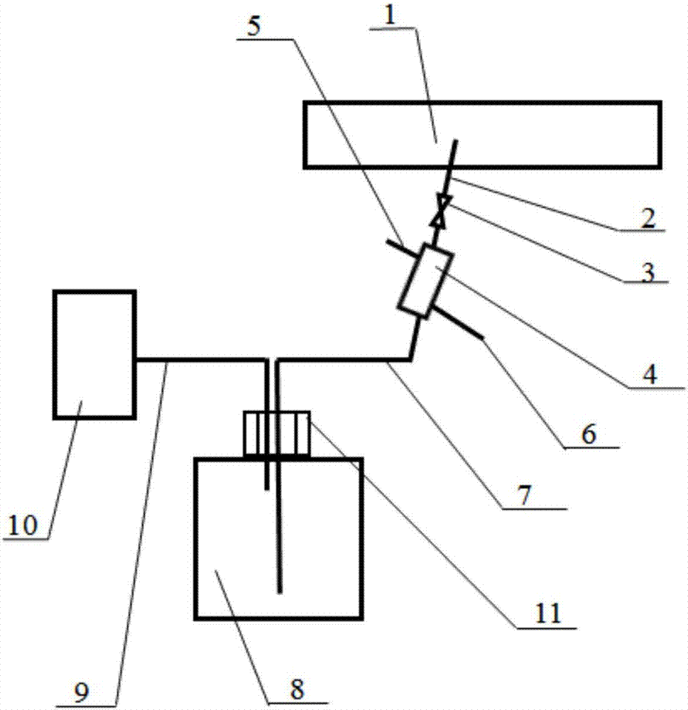
[0025] see figure 1 , a device for measuring the flow of steam and non-condensable gas, the device includes an air induction pipe 7, a cooler, a condensate bottle 8 and a flow meter, wherein one end of the cooler is connected to the air induction pipe 7, and the other end introduces a mixed gas ; The other end of the bleed air pipe 7 is connected to the gas condensate bottle 8;

[0026] Steam and non-condensable gas can flow through the air induction pipe 7 and the cooler, condense after being cooled by the cooler and flow into the condensate bottle 8 for weighing. The non-condensable gas flows through the flow meter to measure the flow rate after passing through the bleed air pipe 7, the condensate gas cylinder 8 and the connecting pipe 9. The device has an ingenious structure, is simple and compact, requires less power, is energy-saving, environment-friendly and low in cost.

[0027] Wherein, in a feasible implementation, the cooler is a cold water jacket 4 , and the cold ...

Embodiment 2

[0036] A device for measuring the flow of steam and non-condensable gas. An exhaust pipe 2 is installed on the main air pipe 1, and an exhaust valve 3 is installed on the pipe. Exhaust pipe 2 is connected with bleed air pipe 7. A cold water jacket 4 is installed on the air-inducing pipe 7, and a water outlet 5 and a water inlet 6 are respectively installed on the cold water jacket 4. The air induction pipe 7 is inserted into the condensate bottle 8, one end of the connecting pipe 9 is connected with the float flowmeter 10, the other end of the connecting pipe 9 is inserted into the condensate bottle 8, the condensate bottle 8, the air induction pipe 7 and the connecting pipe 9 Seal with sealing plug 11.

[0037] The device for measuring steam and non-condensable gas flow of the present invention, when in use:

[0038] When working, the mixed air flow of steam and non-condensable gas flows through the main air pipe 1, and the exhaust valve 3 on the exhaust pipe 2 is opened. T...


PUM


Abstract

The invention provides a device and a method for measuring steam and non-condensable gas flow. The device comprises a gas entraining pipe, a cooler, a gas condensation bottle and a flow meter, one end of the cooler is connected with the gas entraining pipe, mixed gas is leaded into the other end of the cooler, the other end of the gas entraining pipe is connected with the gas condensation bottle, and the gas condensation bottle is sealed and connected with the flow meter through a connecting pipe. The device solves the problem that an existing flow measuring device cannot simultaneously detect steam and non-condensable gas in the mixed gas. The method is simple to operate, accurate in metering and suitable for popularization and application.

Description

technical field [0001] The invention belongs to the technical field of gas flow measurement, and relates to a device and a measurement method for measuring the flow of steam and noncondensable gas. Background technique [0002] Condenser is a commonly used heat exchange equipment in the industrial field. It is a common phenomenon that non-condensable gas is contained in the condenser. This is mainly due to the non-condensable gas dissolved in the working medium or the chemical reaction between the working medium and the pipe to produce non-condensable gas. Therefore, when the mixture of steam and noncondensable gas flows through, the current steam flowmeter or air flowmeter cannot easily identify the respective flow rates of steam and noncondensable gas, but can only measure the total flow rate of the mixture of steam and noncondensable gas. flow. This is extremely inconvenient in experimental measurements and industrial applications. Therefore, it is necessary to propose ...

Claims


Application Information

Patent Timeline
Patent Type & Authority Applications(China)
IPC IPC(8): G01F7/00
CPCG01F7/00
Inventor 张俊霞
Owner YULIN UNIV
Why Eureka
Try Eureka