
Device for performing forced shock excitation on bridge test model

A test model and bridge technology, applied in the field of wind tunnel test, can solve the problems of low excitation frequency and low measurement accuracy of aerodynamic parameters, and achieve the effect of accurate results

Pending Publication Date: 2017-08-18
CENT SOUTH UNIV
View PDF7 Cites 5 Cited by
  • Summary
  • Abstract
  • Description
  • Claims
  • Application Information

AI Technical Summary

Problems solved by technology

[0006] The purpose of the present invention is to provide a device for forced excitation of bridge test models to solve the technical problems of low measurement accuracy of aerodynamic parameters and low excitation frequency in the existing forced vibration method in wind tunnel tests

Method used


Image

  • Device for performing forced shock excitation on bridge test model
  • Device for performing forced shock excitation on bridge test model
  • Device for performing forced shock excitation on bridge test model

Examples


Embodiment Construction

[0026] The embodiments of the present invention will be described in detail below with reference to the accompanying drawings, but the present invention can be implemented in various ways defined and covered by the claims.

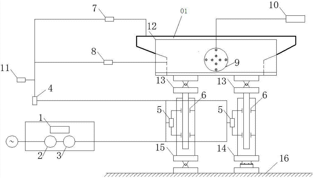
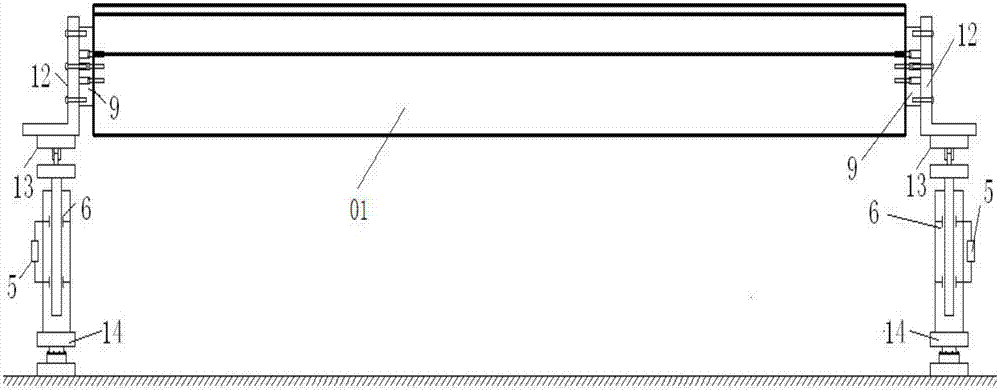
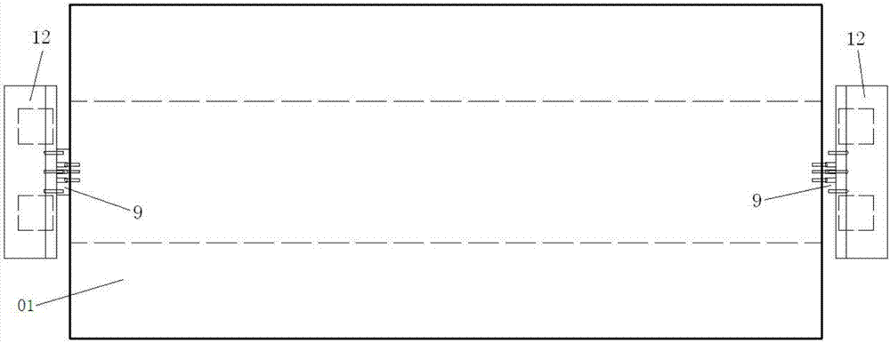
[0027] Such as Figure 1 to Figure 4 As shown, a device for forcing the bridge test model to vibrate, the two ends of the test model 01 in the length direction are respectively provided with a model bracket 12 for supporting the test model, and the end faces of the test model 01 in the length direction are connected to the corresponding Model support 12 is sandwiched with load cell 9, and the circular plane of load cell 9 is arranged in the vertical plane, and described load cell 9 is two and is respectively arranged on the two ends of test model length direction, and the The force sensor 9 is a six-component force balance, and the force sensor is respectively connected to the model support and the test model by bolts.

[0028] Below the four corners in t...


PUM


Abstract

The invention provides a device for performing forced shock excitation on a bridge test model. Two ends of the test model in a length direction are respectively provided with a model support, a force measurement sensor is clamped and disposed between each test model and the corresponding model support, hydraulic oil cylinders with piston rods capable of performing up and down reciprocating motions are respectively disposed below four corners of the test model, and the tops of piston rods of the four hydraulic oil cylinders are respectively connected with an upper movable support seat the top of which is connected with the corresponding model support; the two hydraulic oil cylinders locating below one long edge line of the test model are synchronously telescopic, and the bottoms of the two hydraulic oil cylinders locating below the long edge line of the test model are respectively connected with a lower fixed support seat fixedly connected with a test device foundation; and the two hydraulic oil cylinders locating below the other long edge line are also synchronously telescopic, and the bottoms of the two hydraulic oil cylinders locating below the other long edge line are respectively connected with a lower movable support seat fixedly connected with the test device foundation; and the device further comprises a displacement sensor and an acceleration sensor. The device can simulate a single-DOF (degree of freedom) or coupled forced vibration in a vertical direction and a torsion direction, and the device has the advantages of accurate data and the high shock excitation frequency.

Description

technical field [0001] The invention relates to the field of wind tunnel tests, in particular to a device for forcedly exciting a bridge test model. Background technique [0002] With the rapid development of traffic in the world today, more and more bridges will cross rivers, seas and canyons. The impact of strong winds in these areas on bridges cannot be ignored. As the span of the bridge becomes larger, its flexibility will also increase, and the aeroelastic effect will have a non-negligible impact on the vibration of the structure. [0003] In order to understand the influence of wind load and even the aerodynamic feedback effect on the bridge, we usually conduct tests through wind tunnel tests to obtain the aerodynamic force and aerodynamic parameters of the bridge in the wind field. At present, the methods for obtaining aerodynamic parameters mainly include free vibration method, forced vibration method and random vibration method. [0004] However, the aerodynamic p...

Claims


Application Information

Patent Timeline
Patent Type & Authority Applications(China)
IPC IPC(8): G01M9/08
CPCG01M9/08
Inventor 黄东梅欧俊伟
Owner CENT SOUTH UNIV
Learn More