

Current sensing device based on magnetic field sensing
A technology of sensing device and magnetic field, applied in the direction of measuring device, measuring current/voltage, measuring electrical variable, etc., can solve the problem of affecting the output result, failure to directly protect the fault, etc., to avoid the effect of temperature drift
- Summary
- Abstract
- Description
- Claims
- Application Information
AI Technical Summary
Problems solved by technology
Method used
Image

Examples
specific Embodiment approach 1
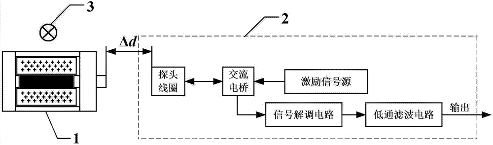
[0025] Specific implementation mode one: combine figure 1 To illustrate this embodiment, a current sensing device based on magnetic field sensing described in this embodiment includes a magnetic field sensing unit (1) and a displacement sensing unit (2);
[0026] The magnetic field sensing unit (1) includes a GMM rod (1-1) and an output rod (1-2), and the GMM rod (1-1) is used to induce the magnetic field of the transmission line to generate axial expansion and contraction, so that the The strain is transmitted to the output rod (1-2);
[0027] The displacement sensing unit (2) includes a probe coil (2-1), an excitation signal source (2-2), an AC bridge (2-3), a signal demodulation circuit (2-4) and a low-pass filter circuit ( 2-5);
[0028] The excitation signal source (2-2) is used to generate a sinusoidal excitation signal, which is loaded to both ends of the probe coil (2-1) through an AC bridge (2-3);
[0029] The probe coil (2-1) is used to sense the axial expansion a...
specific Embodiment approach 2
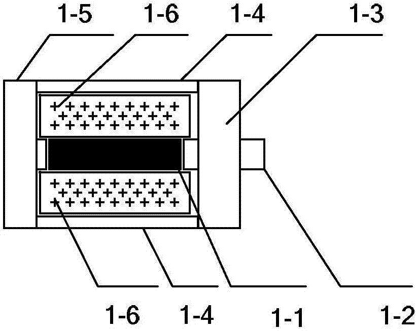
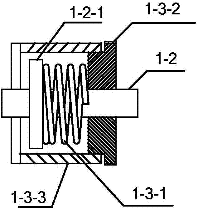
[0032] Specific implementation mode two: combination figure 2 with image 3 This embodiment is described. This embodiment is a further limitation of the current sensing device described in Embodiment 1. In this embodiment, the magnetic field sensing unit (1) further includes a prestressing mechanism (1-3), a bias Magnetic field mechanism, shell (1-4) and base (1-5);
[0033] The base (1-5) and the prestressing mechanism (1-3) are respectively fixed at both ends of the housing (1-4); the GMM rod (1-1) and the biased magnetic field (1-3) and the inside of the space surrounded by the shell (1-4);
[0034] The GMM rod (1-1) is fixed on the base (1-5); the bias magnetic field mechanism includes a permanent magnet (1-6) and a permanent magnet frame for fixing the permanent magnet (1-6), and the permanent magnet (1-6) is used. 6) Wrap around the GMM rod (1-1);
[0035]One end of the output rod (1-2) is fixed on the end face of the GMM rod (1-1), the other end passes through the ...
specific Embodiment approach 3
[0039] Specific implementation mode three: combination Figure 4 This embodiment is described. This embodiment is a further limitation of the current sensing device described in Embodiments 1 and 2. In this embodiment, the excitation signal source (2-2) is realized by using a DDS signal source.
[0040] Such as Figure 4 As shown, the MCU is used to control the DDS, the signal generated by the DDS is amplified by the amplifier, and then loaded to the probe coil (2-1) through the AC bridge (2-3).
[0041] For the current sensing device to work, a signal needs to be applied to the probe coil (2-1), so that an eddy current will be generated in the measured object (output rod (1-2)), and a processable response signal can be provided for the subsequent circuit .
[0042] The excitation signal source (2-2) is used to generate the 1MHz sinusoidal excitation signal required by the current sensing device, and the sinusoidal excitation signal needs to be amplified to the required ampl...
PUM
 Abstract
Description
Claims
Application Information