Bright anti-theft device
An anti-theft device and bright technology, applied in the direction of anti-theft alarms, instruments, alarms, etc., can solve the problems of equipment attack damage, anti-theft device interference, unusable and other problems, and achieve the effect of reliable performance, simple and reliable structure, and easy removal.
- Summary
- Abstract
- Description
- Claims
- Application Information
AI Technical Summary
Problems solved by technology
Method used
Image
Examples
Embodiment 1
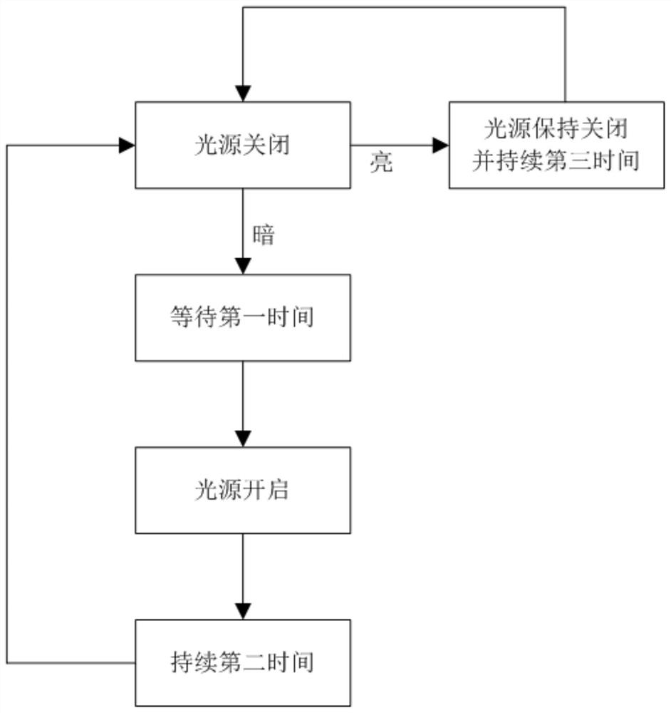
[0074] refer to figure 1 As shown, a bright anti-theft device includes: an executive component 111, a controller and a light sensor 9, the executive component, the executive component is used to turn on or off the light source; the controller, the controller controls the action of the executive component; the light sensor, the light The sensor collects the light and dark signals of the environment, and feeds back the signal to the controller; the executive component can be directly set in the power-on circuit of the light source to realize direct control.
[0075] In order to achieve the effect of automatically switching the light source on and off, the steps for the controller to control the actions of the executive components are as follows:
[0076] Step 1) The light sensor collects the light and dark signals of the environment;
[0077] Step 2) When the light sensor collects that the environment is dark, a feedback signal is sent to the controller, and the controller cont...
Embodiment 2
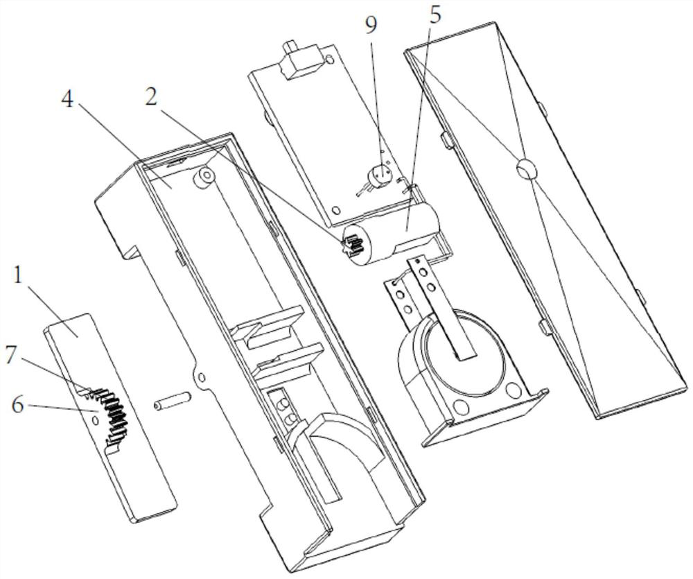
[0084] Embodiment 2 Compared with Embodiment 1, in this embodiment, since the light source in the existing family is basically a lamp, and the switches have been fixed on the wall, in order to adapt to the above situation and improve the application range of the anti-theft device, refer to figure 2 As shown, the execution component performs a switch action, and the switch action is to turn on or turn off the light source, so as to ensure that the anti-theft device can be installed and installed.
[0085] The above-mentioned executive assembly, the executive assembly includes a motor 5, a switch plate 1 and a power output mechanism 2. The power output mechanism is a reduction gear set, a toothed plate 6 is arranged in the middle of the switch plate, and teeth 7 are arranged on the outer circumference of the toothed plate. The gear set is meshed and connected with the teeth; therefore, the gear plate can be rotated along the shaft connection center. When the motor rotates, the r...
Embodiment 3
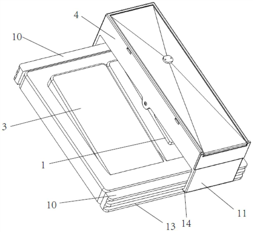
[0089] refer to image 3 and Figure 4 As shown, the difference between the third embodiment and the second embodiment is that a fixing part is provided on the housing bracket, and the fixing part includes two lateral support beams 10 and two support feet 11 that cooperate with the two lateral support beams. The beam is fixedly provided with inserts 12, and the inserts are inserted in the gap between the panel of the switch and the installation part (wall), so that the lateral support beams are fixed, and the two lateral support beams are respectively arranged on the upper and lower parts of the panel, It is suitable for all switch panels with gaps. The surface of the support beam is provided with a guide groove 13, and the support feet are provided with guide hooks 14. After that, it can ensure the structural stability of the upper part and the lower part, the lateral support beam in the lower part will not fall, and also ensure that the support feet can slide in the guide g...
PUM
 Abstract
Description
Claims
Application Information
 - R&D
- Intellectual Property
- Life Sciences
- Materials
- Tech Scout
- Unparalleled Data Quality
- Higher Quality Content
- 60% Fewer Hallucinations
Browse by: Latest US Patents, China's latest patents, Technical Efficacy Thesaurus, Application Domain, Technology Topic, Popular Technical Reports.
© 2025 PatSnap. All rights reserved.Legal|Privacy policy|Modern Slavery Act Transparency Statement|Sitemap|About US| Contact US: help@patsnap.com


