Spring pin complement device for live-line operation of power transmission line

A technology of live work and spring pins, which is applied in the direction of overhead line/cable equipment, pliers, manufacturing tools, etc., can solve the problems of inflexible rotation of the pin removal pliers, increase the difficulty of operation for operators, and offset the position of the pin removal pliers, etc., to achieve The effect of reducing live working time, improving working efficiency and reducing labor intensity

Inactive Publication Date: 2017-08-18
STATE GRID CORP OF CHINA +1
View PDF7 Cites 6 Cited by
  • Summary
  • Abstract
  • Description
  • Claims
  • Application Information

AI Technical Summary

Problems solved by technology

[0002] At present, in the live work of the transmission line, when the insulator bowl head pin is installed and pulled out, the methods used are the equipotential method and the ground potential method. When the ground potential method is used, the operator uses the insulating operating rod and the The pin-removing pliers installed at the front end of the rod are used for operation. During the operation, the jaws of the pin-removing pliers are not easy to align with the bottom opening of the spring pin. The jaws of the pin-removing pliers are clamped by the operator rotating the insulating operating rod. During the process, it is easy to shift the position of the jaws of the pin-removing pliers, and the rotation of the pin-removing pliers is not very flexible, which increases the difficulty of operation for the operator, prolongs the working time, and increases the labor intensity.

Method used


Image

  • Spring pin complement device for live-line operation of power transmission line

Examples


Embodiment Construction

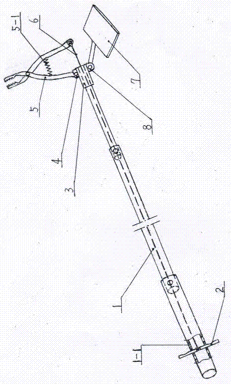
[0009] Examples, see attached figure 1 , On the upper end of the insulating telescopic rod 1 of the live work spring pin take-off device of the transmission line, a connection sleeve 3 is fixedly installed, and the clamp mounting seat 4 and the cardan shaft seat 8 are fixedly equipped with on the connection sleeve 3 respectively. The end observation mirror 7 is equipped with on the universal shaft seat 8, and the end observation mirror 7 can rotate 360 ​​degrees. Compression spring 5-1 is housed between. The tail end of the other clamp handle of the clamp 5 is connected to the upper end of the clamp control stay cord 6, and the lower end of the clamp control stay cord 6 passes through the inner cavity of the insulating telescopic rod 1 and is fixed on the clamp control rod 2, and the clamp control The rod 2 is movably placed in the control rod slot 1-1 of the insulating telescopic rod 1.

[0010] The method of using the spring pin remover for live work on transmission lines ...


PUM


Abstract

The invention belongs to the field of power construction appliances and particularly relates to a spring pin complement device for the live-line operation of a power transmission line. The device comprises an insulating telescopic rod (1) and a clamp (5). The device is characterized in that the upper tip of the insulating telescopic rod (1) is fixedly provided with a connecting sleeve (3). The connecting sleeve (3) is respectively fixed with a clamp installation base (4) and a universal shaft seat (8). The universal shaft seat (8) is provided with a tip observation mirror (7). The clamp installation base (4) is fixedly connected with the tail end of one clamp handle of the clamp (5). A compression spring (5-1) is arranged between the two clamp handles of the clamp (5). The tail end of the other clamp handle of the clamp (5) is connected with the upper end of a control pull rope (6) of the clamp (5). The lower end of the control pull rope (6) of the clamp (5) passes through the inner cavity of the insulating telescopic rod (1) to be fixed onto a clamp control rod (10). The clamp control rod (10) is movably arranged in a control rod clamping groove (1-1) of the insulating telescopic rod (1). The spring pin complement device is simple in structure, and solves the problem in the prior art that spring pins are hard to take and supplement. Meanwhile, the spring pin complement device is convenient to take and operate, and the labor intensity of the operating personnel is reduced. The operation efficiency is improved and the live-line working time is reduced.

Description

technical field [0001] The invention belongs to electric power construction equipment, in particular to a spring pin catcher for live working of power transmission lines. Background technique [0002] At present, in the live work of the transmission line, when the insulator bowl head pin is installed and pulled out, the methods used are the equipotential method and the ground potential method. When the ground potential method is used, the operator uses the insulating operating rod and the The pin-removing pliers installed at the front end of the rod are used for operation. During the operation, the jaws of the pin-removing pliers are not easy to align with the bottom opening of the spring pin. The jaws of the pin-removing pliers are clamped by the operator rotating the insulating operating rod. During the process, it is easy to make the position of the jaws of the pin removal pliers shift, and the rotation of the pin removal pliers is not very flexible, which increases the o...

Claims


Application Information

Patent Timeline
IPC IPC(8): H02G1/02B25B7/00
CPCH02G1/02B25B7/00
Inventor 张国庆卜洪亮叶青杨磊王永灵程大明
Owner STATE GRID CORP OF CHINA
Why Eureka
Try Eureka