
Movement for mechanical timepiece

A technology of mechanical watch and movement, which is applied to the adjustment of mechanically driven clocks, clocks, gear sets, etc., and can solve problems such as waste

Inactive Publication Date: 2017-08-18
CITIZEN WATCH CO LTD
View PDF13 Cites 5 Cited by
  • Summary
  • Abstract
  • Description
  • Claims
  • Application Information

AI Technical Summary

Problems solved by technology

[0013] In addition, the technology proposed in Patent Document 1 also has the problem that, without generating excessive torque, since energy (torque generated by the mainspring) is also consumed in the constant torque mechanism, there is a problem in that the mainspring generates The Problem of Energy Wasted in Constant Torque Mechanism

Method used


Image

  • Movement for mechanical timepiece
  • Movement for mechanical timepiece
  • Movement for mechanical timepiece

Examples


no. 1 approach

[0031]

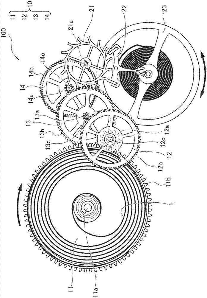
[0032] figure 1 It is a schematic diagram showing a movement 100 of a mechanical portable watch (for example, a wristwatch) as a first embodiment (Embodiment 1) of the present invention.

[0033] The illustrated movement 100 has a mainspring 1 as an example of a power source, a wheel train mechanism 10 , an escape wheel 21 and a pallet fork 22 (escapement mechanism), and a balance wheel 23 (government mechanism). In the gear train mechanism 10, the mainspring 1 is provided inside a rotating barrel 11 as a first wheel.

[0034] The inner end of the mainspring 1 is hung on the barrel center shaft 11a, and the barrel center shaft 11a responds to the winding operation of the crown not shown (in the case of a manual winding type) or the rotation of the rotor (in the case of an automatic winding type). In the case of the wind-up type), the mainspring 1 is wound around the central axis 11a of the mainspring barrel by rotating. In addition, the rotating barrel 11 utilizes...

no. 2 approach

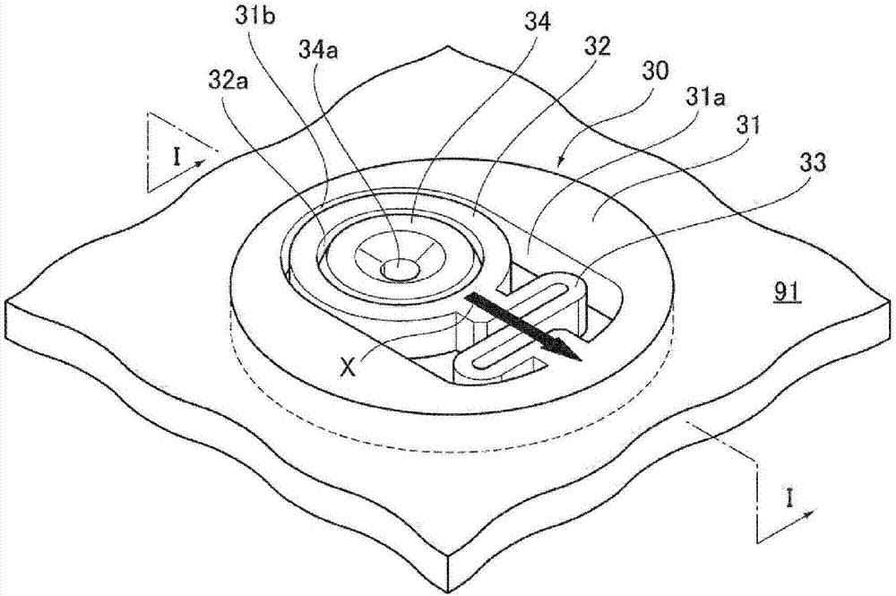
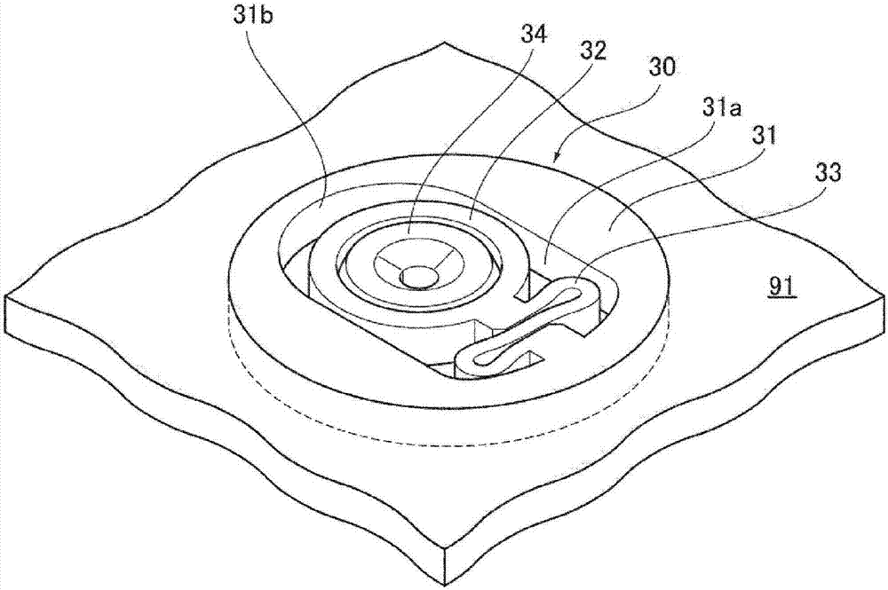
[0093] Figure 6 It is a perspective view showing a spring base 40 as another example of the moving mechanism of the movement of the mechanical watch according to the second embodiment (embodiment 2) of the present invention. Replace with spring part 43 Figure 2A , 2B Except for the spring part 33 in the spring base 30 shown in , the structure of the above-mentioned spring base 40 is the same as that of the spring base 30 .

[0094] The spring portion 33 of the spring base 30 is formed in a substantially “S” shape when viewed from a plan view, but the spring portion 43 of the spring base 40 has an oval ring shape when viewed from a plan view. In addition, the minor axis direction of the elliptical ring shape of the outline of the spring portion 43 is formed along the longitudinal direction X of the elongated hole 31 a.

[0095] In the spring base 40 of Embodiment 2 formed in this way, when the barrel torque does not exceed the predetermined torque Tmax, the base 32 remains...


PUM


Abstract

Provided is a movement wherein, when an excessive torque is generated, transmission of the torque to a speed regulator is suppressed, and when excessive torque is not generated, the wasteful consumption of energy is prevented. A movement (100) is provided with the following: a mainspring (1) (one example of a motive power source) for generating torque; a balance wheel (23) (one example of a speed regulator); a gear train mechanism (10) for transmitting the torque generated by the mainspring (1) to the balance wheel (23); and a spring-equipped base (30) (one example of a mechanism for movement) that, when the torque generated by the mainspring (1) is greater than a torque (Tmax) set beforehand, causes a wheel, such as a second wheel (12), of the gear train mechanism (10) to move in a direction in which torque transmission efficiency between gears of the gear train mechanism (10) decreases.

Description

technical field [0001] The present invention relates to movements of mechanical watches. Background technique [0002] The movement of a mechanical watch has: a power source; a gear train mechanism, which is formed by meshing multiple gears; a speed regulating mechanism and an escapement mechanism, and the gear train mechanism transmits the power generated by the power source to the speed regulating mechanism through the escapement mechanism At the same time, it works with the period adjusted by the speed regulating mechanism. [0003] The power source is, for example, a spring provided in a barrel or the like. In the case of the manual winding type, the user winds the mainspring by turning the crown connected to the winding handle with the finger, and in the case of the self-winding type watch, the mainspring is rotated according to the movement of the watch. The rotor comes rolled up. In addition, the torque generated when the wound mainspring is unwound becomes the pow...

Claims


Application Information

Patent Timeline
Patent Type & Authority Applications(China)
IPC IPC(8): G04B1/22
CPCG04B5/24G04B31/02G04B35/00G04B13/001G04B1/22G04B1/165
Inventor 福田匡广
Owner CITIZEN WATCH CO LTD
Learn More