Optimized parameterization of active disturbance rejection control

A parameter and controller technology, applied in the direction of adaptive control, program control, digital control, etc., can solve problems such as performance degradation and system tuning difficulties

Active Publication Date: 2017-08-18
DANFOSS POWER ELECTRONICS AS
View PDF12 Cites 5 Cited by
  • Summary
  • Abstract
  • Description
  • Claims
  • Application Information

AI Technical Summary

Problems solved by technology

[0005] Adding to these difficulties in achieving optimal controller tuning, some mechanical systems or processes are designed such that there is a considerable delay between a control command issued by the controller and the corresponding system response, this delay is called dead time
Systems with high dead time or phase lag often experience unwanted oscillations in response to disturbances or set point changes, resulting in reduced performance and making tuning such systems more difficult

Method used


Image

  • Optimized parameterization of active disturbance rejection control
  • Optimized parameterization of active disturbance rejection control
  • Optimized parameterization of active disturbance rejection control

Examples


Embodiment Construction

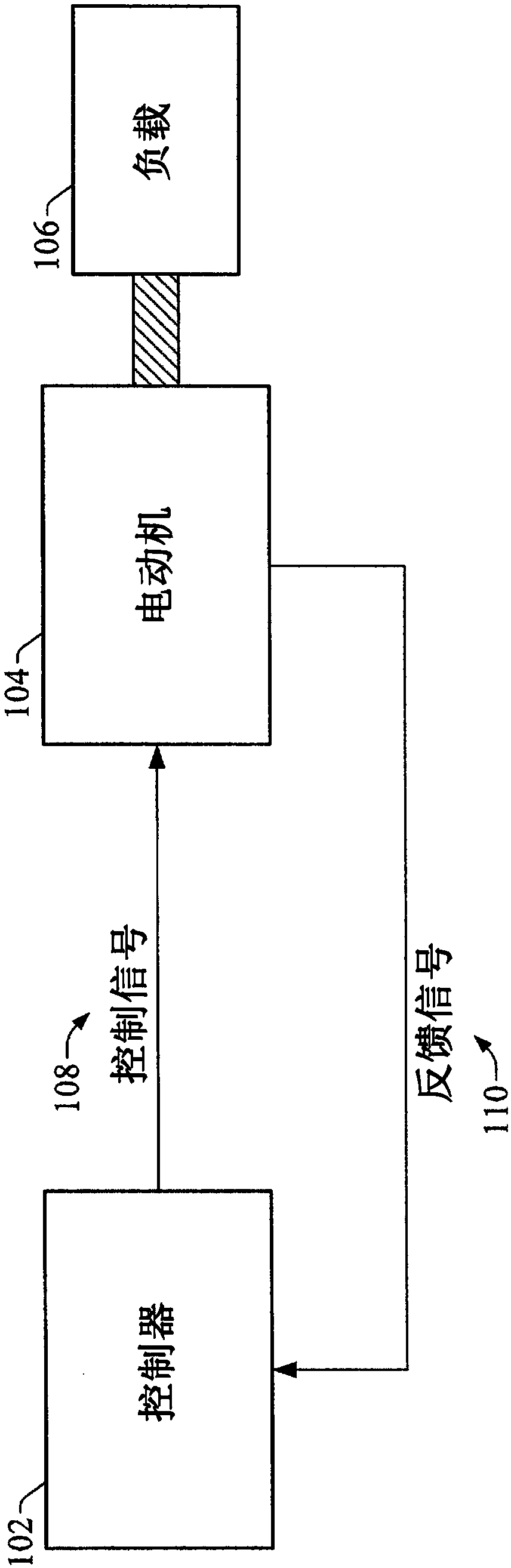
[0021] The systems and methods described herein relate to techniques for reducing or eliminating undesired oscillations in controlled mechanical systems using simplified tuning procedures. According to one or more embodiments, a control method is used to establish the plant parameters of the controlled system and the tuning parameters of the parameterized active disturbance rejection controller determined to be optimal or substantially optimal for the controlled system The relationship between. The object parameters can include the system gain, time constant and dead time of the system such that the identified system dead time is taken into account when establishing these relationships. Corresponding tuning parameters can include controller bandwidth and system gain estimates. Using system gain estimates as tuning parameters as described herein can mitigate the effects of dead time or phase lag on systems controlled using parametric ADRC principles.

[0022] Once these fixed...


PUM


Abstract

A system for tuning a control system uses a simplified tuning procedure to generate robustly stabilizing tuning parameters that reduce or eliminate undesired system oscillations in the presence of long system dead times or phase lag. A control method is used to establish a relationship between the plant parameters of a controlled system and the tuning parameters of a parameterized active disturbance rejection controller determined to be optimal or substantially optimal for the control system. The plant parameters include the system gain, the time constant, and dead time. Corresponding tuning parameters include the controller bandwidth and a system gain estimate. Using the system gain estimate as a tuning parameter can alleviate the influence of large dead times or phase lags on system response. Once established, these fixed relationships can be used to determine suitable tuning parameters for specific motion or process control applications based on the system gain and dominant constraints of the system.

Description

technical field [0001] In general, the present disclosure relates to motion control, and in particular, to automatically determining tuning parameters for a control system given the system gains and prevailing constraints of the system. Background technique [0002] Many automation applications employ motion control systems to control machine position and speed. Such motion control systems typically include one or more electric motors or other motion devices operating under the direction of a controller that sends position or velocity control commands to the motors according to a user-defined control algorithm. Some motion control systems operate in a closed-loop configuration whereby the controller instructs the motor to move to a target position or transition to a target speed (desired state) and receives feedback information indicative of the actual state of the motor. The controller monitors this feedback information to determine whether the motor has reached a target p...

Claims


Application Information

Patent Timeline
Patent Type & Authority Applications(China)
IPC IPC(8): G05B13/02
CPCG05B13/024G05B19/416G05B2219/41025
Inventor 田刚艾哈迈德·沙伊尔吉里什·亚约维迪
Owner DANFOSS POWER ELECTRONICS AS
Why Eureka
Try Eureka