
Spark plug and method for producing a spark plug

A spark plug and center electrode technology, applied in the field of spark plug manufacturing, can solve the problem of high spark plug wear, and achieve the effects of reducing heat dissipation and improving service life

Active Publication Date: 2017-08-18
ROBERT BOSCH GMBH
View PDF11 Cites 2 Cited by
  • Summary
  • Abstract
  • Description
  • Claims
  • Application Information

AI Technical Summary

Problems solved by technology

Therefore, the wear of such spark plugs through thermal overload is high

Method used


Image

  • Spark plug and method for producing a spark plug
  • Spark plug and method for producing a spark plug

Examples


Embodiment Construction

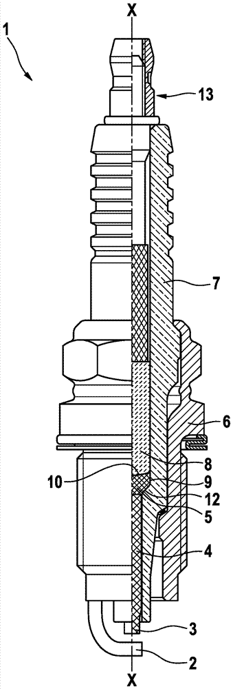
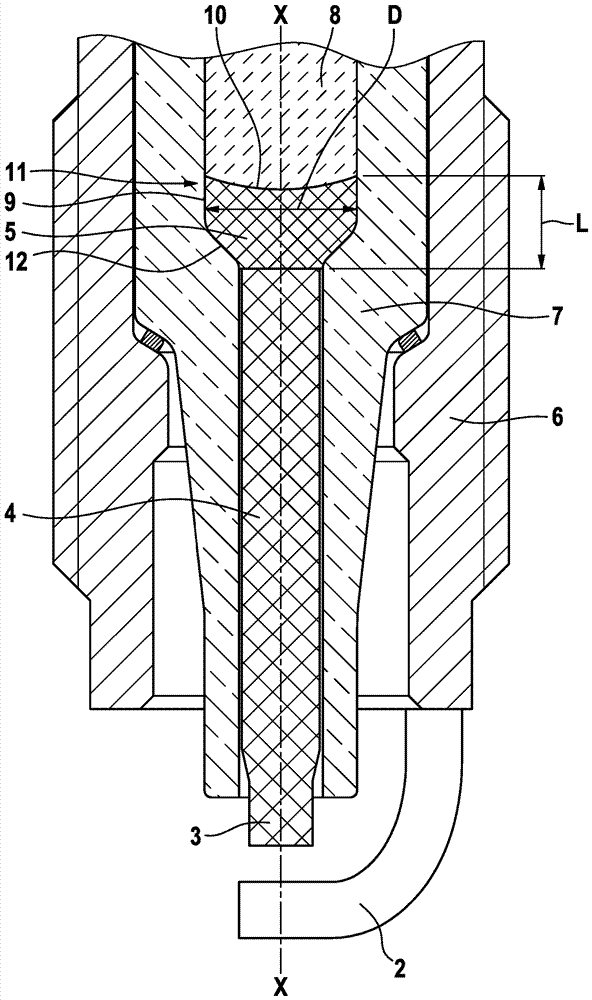
[0023] As can be seen from 1 , spark plug 1 comprises a ground electrode 2 and a center electrode 3 . The ceramic insulator 7 is arranged in such a way that the center electrode 3 protrudes slightly from the insulator 7 in a known manner. The center electrode 3 is produced from one material, but can of course also have a core-sheath structure, for example with a sheath of a material containing nickel and a core of a material containing copper, which improves the connection from the base of the center electrode towards the combustion chamber to the insulator. 7 on heat transport. Furthermore, noble metal pins can be provided on the combustion chamber side for generating the spark plasma.

[0024] The insulator 7 itself is partially surrounded by the housing 6 . Reference numeral 13 designates an electrical connection region of spark plug 1 . An electrically conductive connection to the central electrode 3 is provided from the electrical connection region 13 via the connectio...


PUM


Abstract

The present invention relates to a spark plug (1) with improved heat-dissipating capacity of the central electrode. According to the invention, the spark plug (1) comprises a ground electrode (2), a central electrode (3) and a ceramic insulator (7) which is configured to hold the central electrode (3). The central electrode (3) comprises a central electrode head (5) located in the direction of an electrical connection region (13) of the spark plug (1), which comprises a front side (10) which is in contact with an electrically conductive connecting element (8) arranged between the electrical connection region (13) and the central electrode head (5). The central electrode head (5), on the outer circumference thereof, is in heat-conducting contact at least in sections with the ceramic insulator (7) and forms a heat-conducting contact region (9).

Description

technical field [0001] The invention relates to a spark plug with reduced wear on the center electrode and to a simple and practicable method for producing the spark plug. Background technique [0002] Spark plugs of various designs are known from the prior art. WO 2012 / 105255 A 1 describes a spark plug with a center electrode and a ground electrode. The center electrode is arranged in an insulator. The electrically conductive material makes the electrical connection between the center electrode of the spark plug and the electrical connection area. In this case, the electrically conductive material surrounds the central electrode head of the central electrode, which is oriented in the direction of the electrical connection region, and fills the gap between the central electrode head and the insulator. The electrically conductive material acts as a thermal insulator and prevents or reduces heat dissipation from the center electrode via the ceramic insulator to the cooled c...

Claims


Application Information

Patent Timeline
Patent Type & Authority Applications(China)
IPC IPC(8): H01T13/16H01T21/02
CPCH01T13/16H01T21/02H01T13/34
Inventor N.克劳斯C.希梅尔
Owner ROBERT BOSCH GMBH
Learn More