
Ultrasonic welding device for fabric processing

An ultrasonic welding and fabric technology, which is applied in the field of ultrasonic welding devices for fabric processing, can solve the problems of imprecise welding, poor thermal conductivity, and gaps between cloth and cloth, and achieve the effects of eliminating air gaps, reducing wear rates, and eliminating air gaps

Pending Publication Date: 2022-08-09
四川邦尼德织物有限公司
View PDF0 Cites 0 Cited by
  • Summary
  • Abstract
  • Description
  • Claims
  • Application Information

AI Technical Summary

Problems solved by technology

[0003] At present, textile enterprises usually use ultrasonic welding devices to replace traditional welding devices when welding cloth. , so that wrinkles are prone to appear between the cloth, so that when the welding operation is performed, there will be a gap between the cloth and the cloth, resulting in imprecise welding and reducing the welding quality
[0004] The ultrasonic welding device in the prior art, when welding the cloth, uses high-frequency vibration to generate high temperature through friction between the cloth and the cloth. Due to the poor thermal conductivity of the cloth, the high temperature is not easy to dissipate, thereby realizing welding. effect, but because the high temperature is not easy to dissipate, the fixation of the newly welded interface is not reliable, and it is easy to separate, and after a long period of continuous operation, the temperature of the lower pressure head is too high, which intensifies the wear of the lower pressure head and reduces the service life
[0005] When the ultrasonic welding device in the prior art is welding the cloth, one end of the two sections of cloth is superimposed and placed on the welding table. It is easy for the fabric to accidentally slip before welding, and manual support is required, which increases the workload of the staff and is not convenient for the staff to use

Method used


Image

  • Ultrasonic welding device for fabric processing
  • Ultrasonic welding device for fabric processing
  • Ultrasonic welding device for fabric processing

Examples


Embodiment Construction

[0028] The technical solutions in the embodiments of the present invention will be clearly and completely described below with reference to the accompanying drawings in the embodiments of the present invention. Obviously, the described embodiments are only a part of the embodiments of the present invention, but not all of the embodiments. Based on the embodiments of the present invention, all other embodiments obtained by those of ordinary skill in the art without creative efforts shall fall within the protection scope of the present invention.

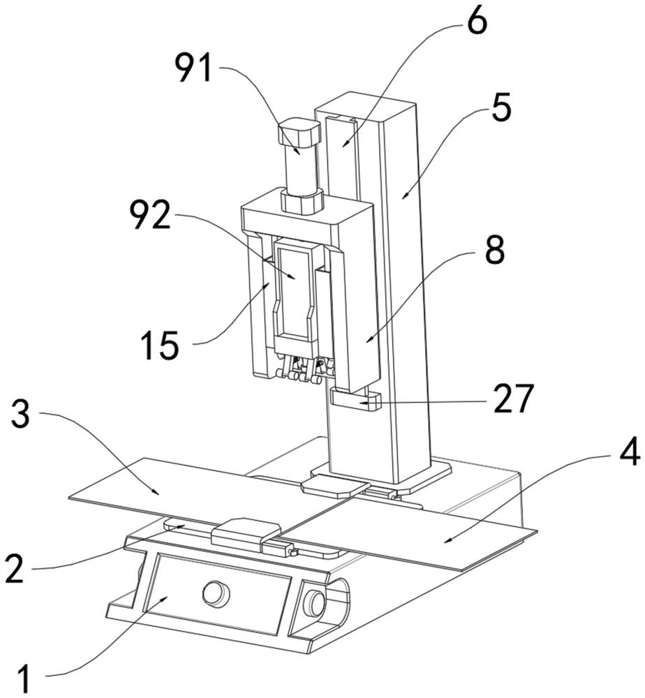
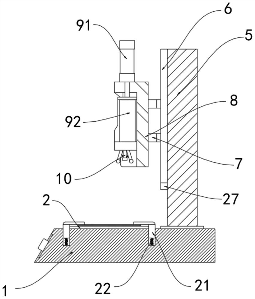
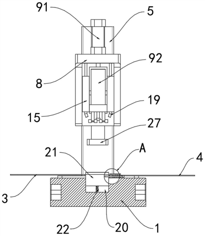
[0029] like Figure 1 to Figure 8 As shown, the embodiment of the present invention provides an ultrasonic welding device for fabric processing, including a base 1, a welding table 2 is fixedly installed on the top of the base 1, and a first cloth 3 and a second cloth are placed on the left and right ends of the top of the welding table 2, respectively. Two fabrics 4, one end of the first fabric 3 and the second fabric 4 are stacked t...


PUM


Abstract

The invention belongs to the technical field of ultrasonic welding, and discloses an ultrasonic welding device for fabric processing, which comprises a base, a welding table is fixedly mounted at the top of the base, first cloth and second cloth are respectively placed at the left end and the right end of the top of the welding table, and a supporting rod is fixedly mounted at the top of the base. A sliding rail is fixedly mounted on the front face of the supporting rod, and a first movable block is slidably mounted at the left end of the sliding rail. According to the device, the pulleys and the ultrasonic device are arranged, the first cloth and the second cloth are pulled to the two sides through the pulleys, the surfaces of the first cloth and the second cloth are flatly laid, and compared with a traditional device, the device can flatly lay the first cloth and the second cloth before welding, so that the welding efficiency is improved; the air gap between the first cloth and the second cloth is eliminated, the first cloth and the second cloth are prevented from wrinkling, and the air gap during welding is completely eradicated.

Description

technical field [0001] The invention belongs to the technical field of ultrasonic welding, in particular to an ultrasonic welding device for fabric processing. Background technique [0002] With the rapid development of society, food, clothing, housing and transportation are indispensable in people's lives, thus promoting the rapid development of the textile industry, making textiles enter the ultrasonic welding device. The ultrasonic welding device emits ultrasonic waves through an ultrasonic transmitter, and then passes through an energy converter. , so that the ultrasonic wave is converted into high-frequency vibration, and through the vibration, the fabrics are under the action of friction, resulting in high temperature and fusion between the fabrics. [0003] At present, textile enterprises usually use ultrasonic welding devices to replace traditional welding devices when welding fabrics. , which makes it easy to have wrinkles between the fabrics, so that during the we...

Claims


Application Information

Patent Timeline
IPC IPC(8): B29C65/08B29C65/78
CPCB29C65/08B29C65/7841B29C66/022B29C66/0342
Inventor 梅兴波孙成喜张施林
Owner 四川邦尼德织物有限公司
Learn More