Eureka AIR delivers breakthrough ideas for toughest innovation challenges, trusted by R&D personnel around the world.

Special automatic production line for drilling of oil pump rotor type workpieces

An automatic production line and workpiece technology, applied in the direction of boring/drilling, drilling/drilling equipment, metal processing, etc., can solve the problems of high labor cost, low processing efficiency, high cost, etc., to ensure repeat positioning accuracy, improve The level of automation, the effect of increasing the degree of automation

Active Publication Date: 2017-08-22
YANGZHOU UNIV
View PDF6 Cites 4 Cited by
  • Summary
  • Abstract
  • Description
  • Claims
  • Application Information

AI Technical Summary

Problems solved by technology

At present, for the drilling, deburring, and chamfering of oil pump rotor workpieces, most of the machining centers are used to drill, deburr, and chamfer each hole in turn. The cost of the machining center is relatively high, and this The efficiency of this processing method is low. In addition, there is a method of using tools such as drill sets to process workpieces manually. The disadvantages of this processing method are still low processing efficiency and high labor costs.
There are many turnover processes for oil pump rotor workpieces. After multiple clampings, the machining accuracy of the workpiece holes cannot be guaranteed, and the position of the workpiece holes is also unstable.

Method used


Image

  • Special automatic production line for drilling of oil pump rotor type workpieces
  • Special automatic production line for drilling of oil pump rotor type workpieces
  • Special automatic production line for drilling of oil pump rotor type workpieces

Examples


Embodiment Construction

[0023] In order to further clarify the technical solution of the present invention, the present invention will be further introduced below in conjunction with the accompanying drawings and specific embodiments.

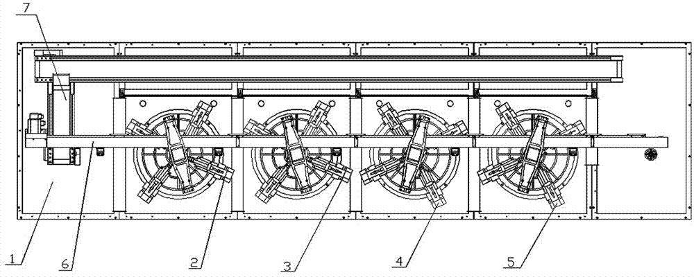
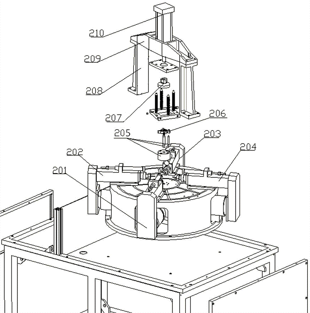
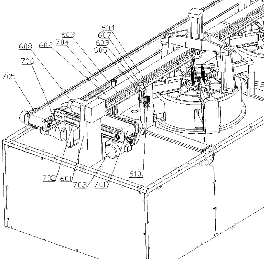
[0024] like Figure 1 to Figure 5 As shown, an automatic production line dedicated to drilling oil pump rotor workpieces, including a bed 1, a drilling module group, a truss manipulator 6, a gantry-type pneumatic pressing device, and a workpiece receiving and conveying mechanism 7 and other components. In this embodiment, the workpiece 206, as shown in 6, includes a cylindrical base and protruding teeth protruding from the periphery of the base. The workpiece 206 is provided with two groups of holes A and B along the circumference, not at the same height, distributed On both sides of the protruding teeth, the holes in group A and group B are composed of four uniformly distributed unit holes.

[0025] The base 101 of the bed 1 is provided with four workbenches arrange...


PUM


Abstract

The invention discloses a special automatic production line for drilling of oil pump rotor type workpieces. Component parts comprising a boring machine body, a drilling module set, a truss manipulator, a gantry air clamper, a workpiece material collecting and conveying mechanism and the like are arranged. According to the special automatic production line disclosed by the invention, the workpieces are transferred between service positions through the synchronous manipulator, so that the linear continuous processing of the workpieces is realized, and the automation level of integral production is increased; drilling and chamfering are all synchronously performed on each processing service position by a plurality of drilling main shafts, so that the stability of the location degree of a hole in each workpiece is guaranteed; the special automatic production line adopts a positioning manner of a plane and two pits and the gantry air clamper for the workpieces, so that the repeated positioning accuracy of the workpieces can be guaranteed, and the stability of the locating degree of the workpieces is further guaranteed; and through the workpiece material collecting and conveying mechanism, the processed workpieces are transported to a material collecting service position to be processed in a centralized manner, so that the automation degree of production of the workpieces is increased.

Description

technical field [0001] The invention relates to the technical field of mechanical processing, and specifically relates to a special automatic production line for drilling oil pump rotor workpieces. Background technique [0002] There are two groups of holes arranged in a circular array on the side of the oil pump rotor workpiece. These two groups of holes are distributed at different heights of the workpiece, and each group of holes has three to five holes. At present, for the drilling, deburring, and chamfering of oil pump rotor workpieces, most of the machining centers are used to drill, deburr, and chamfer each hole in turn. The cost of the machining center is relatively high, and this This processing method is less efficient. In addition, there is a method of using tools such as drill sets to process workpieces manually. The disadvantages of this processing method are still low processing efficiency and high labor costs. There are many turnover processes for oil pump ro...

Claims


Application Information

Patent Timeline
Patent Type & Authority Applications(China)
IPC IPC(8): B23B39/16B23B39/20B23Q7/14
CPCB23B39/168B23B39/205B23Q7/1447
Inventor 王心成包尊萍李鹭扬
Owner YANGZHOU UNIV
Why Eureka
Eureka Blog
Learn More