Establishing method for thermal error identification model of machine tool working space

A technology of working space and establishing method, which is applied in the direction of manufacturing tools, metal processing, metal processing equipment, etc., can solve the problems of long time-consuming temperature measurement, hysteresis of thermal error measurement results, and inability to accurately reflect the thermal error of machine tools in real time, etc., to achieve The effect of fast and convenient measurement operation, fast identification and high identification accuracy

Inactive Publication Date: 2017-08-22
TIANJIN UNIV
View PDF5 Cites 14 Cited by
  • Summary
  • Abstract
  • Description
  • Claims
  • Application Information

AI Technical Summary

Problems solved by technology

The direct method uses a laser interferometer to directly measure the individual thermal errors of each axis. However, due to the large number of thermal error items of the machine tool, it is difficult for this type of method to measure all individual thermal errors; the indirect method first establishes the thermal error-temperature mapping. model, and then solve the single thermal error of each axis by detecting the temperature of each key point of the machine tool. This type of method can realize thermal error identification with a certain accuracy, but because the mapping model between thermal error and temperature is nonlinear, and the temperature measurement consumes The time is long, so the thermal error measurement results have hysteresis, which makes this type of method unable to accurately reflect the thermal error of the machine tool in real time

Method used


Image

  • Establishing method for thermal error identification model of machine tool working space
  • Establishing method for thermal error identification model of machine tool working space
  • Establishing method for thermal error identification model of machine tool working space

Examples


Embodiment Construction

[0033] In order to further understand the invention content, characteristics and effects of the present invention, the following examples are given, and detailed descriptions are as follows in conjunction with the accompanying drawings:

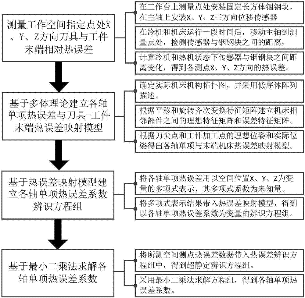
[0034] see figure 1 , a method for establishing a thermal error identification model of a machine tool workspace, comprising the following steps:

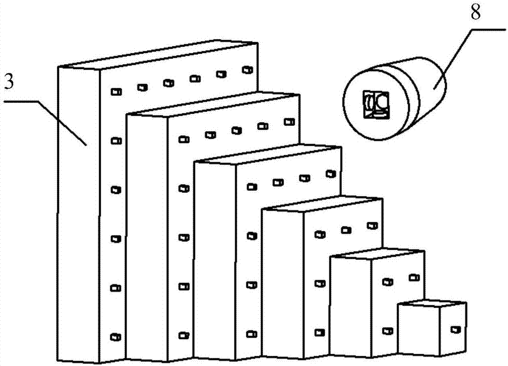
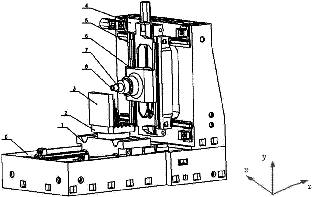
[0035] Step 1: Measure the relative thermal error between the tool and the end of the workpiece in the X, Y, and Z directions at the specified point in the workspace;

[0036] Step 2: Based on the multi-body theory, establish a mapping model of the single thermal error of each axis and the thermal error of the end;

[0037] Step 3: Express the individual thermal errors of each axis with polynomials, and establish a system of identification equations for the individual thermal error coefficients of each axis based on the thermal error mapping model;

[0038] Step 4: Solve the individual thermal e...


PUM


Abstract

The invention discloses an establishing method for a thermal error identification model of machine tool working space. The establishing method comprises the following steps: step I: measuring relative thermal errors of tools in the X direction, the Y direction and the Z direction at a specified point of working space and the tail end of a workpiece; step II: establishing a mapping model between single thermal error of each axle and thermal errors of the tail end based on a many-body theory; step III: expressing single thermal error of each axle through a polynomial, and establishing a single thermal error coefficient identification equation set of each axle based on the thermal error mapping model; and step IV: dissolving a single thermal error coefficient of each axle based on a least square method, and identifying single thermal error, expressed through the polynomial, of each axle. The establishing method can realize quick identification for the single thermal error of each axle through thermal error measurement of the tool at each point of the machine tool working space and the tail end of the workpiece, is quick and convenient to measure and operate, and is high in identification precision.

Description

technical field [0001] The invention relates to a thermal error modeling method of a machine tool, in particular to a method for establishing a thermal error identification model of a machine tool working space. Background technique [0002] In recent years, the technology of CNC machine tools in my country's manufacturing industry has developed rapidly, but the thermal errors caused by heat sources inside and outside the machine tools have seriously restricted the improvement of machine tool machining accuracy. Studies have shown that in the process of high-speed and high-precision CNC machine tool processing, the errors caused by the heating of various components of the CNC machine tool account for more than 40% of the total error. Therefore, how to quickly identify and compensate the individual thermal errors of each axis is the key to improving the machining accuracy of CNC machine tools. At present, there are two main methods to obtain the single thermal error of each ...

Claims


Application Information

Patent Timeline
Patent Type & Authority Applications(China)
IPC IPC(8): B23Q17/22B23Q15/18
CPCB23Q17/22B23Q15/18
Inventor 张大卫蔡翔高卫国刘兴国王佳王伟松刘兴兴
Owner TIANJIN UNIV
Why Eureka
Try Eureka