Efficient grinding and rust removing equipment for steel bars for building

A technology for construction and steel bars, applied in grinding/polishing equipment, metal processing equipment, grinding machines, etc., can solve the problems of low grinding efficiency, affecting structural safety, high production cost, etc., and achieve the effect of improving grinding efficiency

Inactive Publication Date: 2017-08-22
长沙鼎成新材料科技有限公司
View PDF0 Cites 41 Cited by
  • Summary
  • Abstract
  • Description
  • Claims
  • Application Information

AI Technical Summary

Problems solved by technology

[0004] The steel bars on the construction site are placed in the open air and exposed to the sun and rain. After a long time, the surface of the steel bars is prone to rust. If it is not treated in time, it is easy to continue to corrode to the inside of the steel bars, affecting the bearing capacity of the steel bars, thereby affecting the structural safety and causing safety accidents. At present There are mainly two methods of manua

Method used


Image

  • Efficient grinding and rust removing equipment for steel bars for building
  • Efficient grinding and rust removing equipment for steel bars for building
  • Efficient grinding and rust removing equipment for steel bars for building

Examples


Embodiment 1

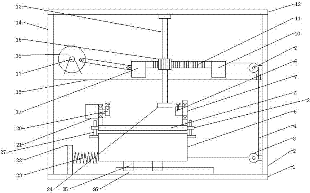
[0020] see Figure 1~2 , in the embodiment of the present invention, a kind of high-efficiency grinding and derusting equipment for steel bars for construction includes a bottom plate 1, a workbench 6 and a grinding disc 24, the upper left side of the bottom plate 1 is provided with a left side Side plate 2, top plate 12 is fixed on the top of left side plate 14 and right side plate 2, and slide rail 26 is arranged in the middle of described base plate 1 top, slide rail 26 is slidably connected with first slide block 25, and first slide block 25 is fixed. At the bottom of the box body 5, a first spring 23 is connected to the lower left part of the box body 5, and the other end of the first spring 23 is connected to the fixed rod 22 on the bottom plate 1. A workbench 6 is arranged above the box body 5, and both sides of the lower part of the workbench 6 A sleeve 28 is provided, and a slide bar 27 is set inside the sleeve 28. The bottom end of the slide bar 27 is fixedly connect...

Embodiment 2

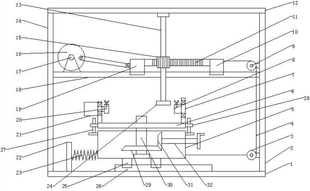
[0022] see image 3, based on Embodiment 1, a second bearing seat is installed at the bottom of the inner cavity of the box body 5, a threaded rod 30 is installed on the second bearing seat, and a first helical gear 29 is installed on the bottom of the threaded rod 30, and the first helical gear 29 and The second helical gear 31 is meshed, and a connecting shaft 32 is fixed in the middle of the right side wall of the second helical gear 31. The other end of the connecting shaft 32 runs through the box body 5 and is connected with the rotating handle. The connecting shaft 32 is rotatably connected with the box body 5. The threaded rod The top of 30 runs through the box body 5 and the workbench 6 and is spirally connected with the workbench 6. The threaded rod 30 is rotatably connected with the box body 5. When the handle is rotated, the handle drives the connecting shaft 32 to rotate, and the connecting shaft 32 drives the second helical gear 31 to rotate. , the second helical ...


PUM


Abstract

The invention discloses a high-efficiency grinding and derusting equipment for steel bars for construction, which comprises a bottom plate, a left side plate, a right side plate, a top plate, a slide rail, a first slider, a box body, a first spring, a workbench, a sleeve, a slide Rod, mounting plate, first motor, first clamping device, second clamping device, horizontal support plate, second motor, disc, connecting rod, second slider, rack, third slider, pull cord , the first fixed pulley, the second fixed pulley, racks, gears, rotating shafts, and grinding discs. The present invention is provided with a first clamping device and a second clamping device, which can fix steel bars of different diameters. The first motor, the second motor, the disc, the second slider, the rack, the gear, the third slider, the pull rope, the box body and the spring, through the cooperation of the above components, the steel bar can be polished in all directions, which further improves the grinding efficiency , with a first helical gear, a second helical gear and a threaded rod to adjust the distance between the workbench and the grinding disc to accommodate steel bars of different diameters.

Description

technical field [0001] The invention relates to the technical field of construction equipment, in particular to high-efficiency grinding and derusting equipment for steel bars used in construction. Background technique [0002] Architecture is a kind of space for people to live and use composed of building materials such as mud, bricks, tiles, stones, and wood, such as houses, bridges, factories, gymnasiums, caves, water towers, temples, etc. [0003] Reinforcement refers to steel for reinforced concrete and prestressed reinforced concrete, which is circular in cross-section and sometimes square with rounded corners. Including plain round bars, ribbed bars, twisted bars. Steel bars for reinforced concrete refer to the straight or coiled steel used for reinforced concrete reinforcement. Its shape is divided into two types: smooth round steel bar and deformed steel bar. The delivery state is straight bar and coiled round. [0004] The steel bars on the construction site are ...

Claims


Application Information

Patent Timeline
IPC IPC(8): B24B27/033B24B41/06B24B41/02B24B47/04B24B47/12B24B47/16
CPCB24B27/033B24B41/02B24B41/067B24B47/04B24B47/12B24B47/16
Inventor 彭小红
Owner 长沙鼎成新材料科技有限公司
Why Eureka
Try Eureka