Gasification burner device
A pulverized coal and sprinkler technology, which is applied in the details of gasification device, gasification process, granular/powder fuel gasification, etc., can solve the problems of uneven circumferential distribution of pulverized coal, increased system control difficulty, and increased cost, etc. Achieve the effect of eliminating the poor uniform distribution effect of pulverized coal, improving the uniform distribution effect, and increasing kinetic energy
- Summary
- Abstract
- Description
- Claims
- Application Information
AI Technical Summary
Problems solved by technology
Method used
Image
Examples
Embodiment 1
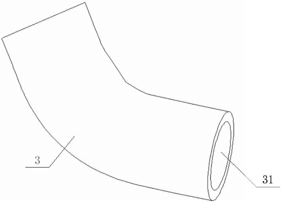
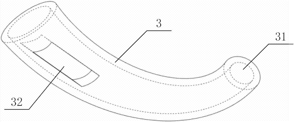
[0035] refer to image 3 , Figure 5 and Figure 6 , the pulverized coal nozzle in this embodiment is an elbow whose pipe diameter gradually decreases from top to bottom, the lower end of the elbow is the lower end pulverized coal nozzle 31, and at least one side opening Coal nozzle 32, and said side-opened pulverized coal nozzle 32 is a slanted port that gradually slopes outward along the airflow advancing direction.
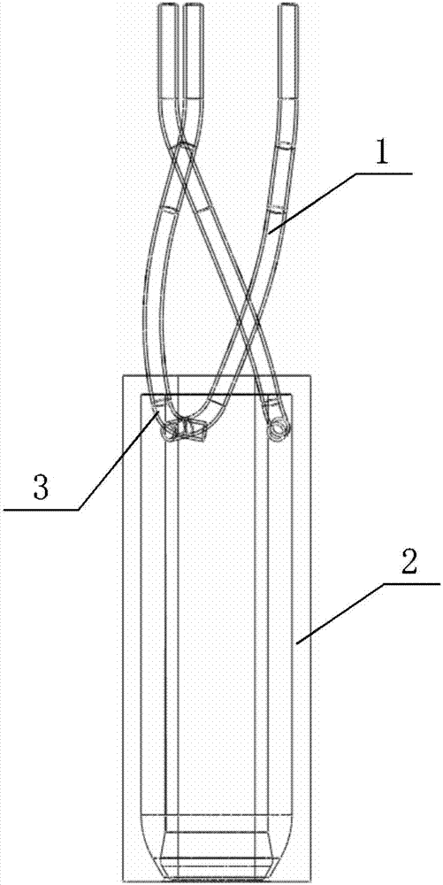
[0036] Moreover, this embodiment also provides a gasification burner device including the above-mentioned spray head 3 . Specifically, the gasification burner device also includes a pulverized coal delivery pipe 1 and an annular pulverized coal cavity 2 . Wherein, each part of this gasification burner device can specifically include the following:
[0037] 1) The nozzle 3 is an elbow whose pipe diameter gradually decreases from top to bottom, and the upper end of the elbow communicates with the pulverized coal delivery pipe 1, and the lower end is the lower...
Embodiment 2
[0051] The existing gasification burner device and the gasification burner device provided by the embodiments of the present invention are subjected to the following comparative experiments:
[0052] Divide the pulverized coal ejected from the nozzle of the gasification burner device into 12 equal parts in the circumferential direction, and count the proportion of pulverized coal in each part, so as to obtain the following Figure 7 The comparison diagram of the uniform distribution effect of the powder sprayed by the gasification burner device shown.
[0053] Figure 7 The flatter the curve in the figure, the better the uniform distribution of the powder around the circumference. Depend on Figure 7 It can be seen that the gasification burner device provided by the embodiment of the present invention is much better than the existing gasification burner device in the uniform distribution of pulverized coal sprayed from the nozzle in the circumferential direction.
Embodiment 3
[0055] The existing gasification burner device and the gasification burner device provided by the embodiment of the present invention were subjected to the following comparative experiments: using one pulverized coal conveying pipe and three pulverized coal conveying pipes to feed pulverized coal respectively, and detecting the relative standard deviation , so that the results shown in the following table 1 can be obtained:
[0056] Table 1 The gasification burner device of the prior art and the effect comparison of the gasification burner device of the present invention
[0057]
[0058] It can be seen from Table 1 that, compared with the existing gasification burner, the relative standard deviation of the gasification burner device provided by the embodiment of the present invention can be reduced from 80.9% when one pulverized coal delivery pipe is used to feed the pulverized coal. to 17.2%, and when using the three-way pulverized coal delivery pipe to feed the powder, t...
PUM
 Abstract
Description
Claims
Application Information
 - R&D
- Intellectual Property
- Life Sciences
- Materials
- Tech Scout
- Unparalleled Data Quality
- Higher Quality Content
- 60% Fewer Hallucinations
Browse by: Latest US Patents, China's latest patents, Technical Efficacy Thesaurus, Application Domain, Technology Topic, Popular Technical Reports.
© 2025 PatSnap. All rights reserved.Legal|Privacy policy|Modern Slavery Act Transparency Statement|Sitemap|About US| Contact US: help@patsnap.com


