Hydraulic cylinder type water drainage-gas recovery device

A drainage gas recovery and hydraulic cylinder technology, which is applied in the direction of mining fluid, earthwork drilling, wellbore/well components, etc., can solve the problem of not fully meeting the technical requirements of gas lift drainage and gas recovery, increasing the input cost of gas production, high-pressure gas The number of source wells is limited and other issues, to achieve the effect of increasing gas production, reducing losses, and compact structure

Inactive Publication Date: 2017-08-22
四川瑞晟石油设备开发有限公司
View PDF0 Cites 3 Cited by
  • Summary
  • Abstract
  • Description
  • Claims
  • Application Information

AI Technical Summary

Problems solved by technology

However, the number of high-pressure gas source wells is currently limited, which cannot fully meet the technical requirements of gas lift drainage and gas recovery
[0004] In addition, the drainage gas recovery device used in the foam drainage gas recovery process

Method used


Image

  • Hydraulic cylinder type water drainage-gas recovery device

Examples


Embodiment Construction

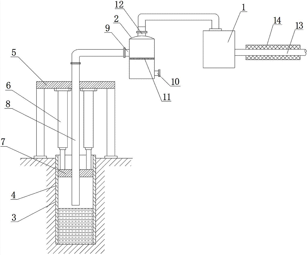
[0013] The present invention will be further described below in conjunction with accompanying drawing, protection scope of the present invention is not limited to the following:

[0014] Such as figure 1 As shown, a hydraulic cylinder type drainage gas recovery device, which includes a natural gas compressor 1, a gas-liquid separation tank 2 and a shaft 4 arranged in a gas well 3, the wellhead of the gas well 3 is provided with a gantry 5, a gantry An oil cylinder 6 is fixedly installed on the crossbeam of the frame 5, and the piston rod of the oil cylinder 6 is provided with a gland 7 that can slide up and down along the wellbore 4. A sliding seal is formed between the gland 7 and the inner wall of the wellbore 4, which can prevent gas wells from The liquid leaks from the gap between the gland 7 and the wellbore 4, which has the characteristics of tight sealing.

[0015] Such as figure 1 As shown, the crossbeam of the gantry frame 5 is also fixed with a delivery pipe 8 pass...


PUM


Abstract

The invention discloses a hydraulic cylinder type drainage gas recovery device, which comprises a natural gas compressor (1), a gas-liquid separation tank (2), a shaft (4) arranged in a gas well (3), and a gantry (5) beam An oil cylinder (6) is fixedly installed on the top, and the piston rod of the oil cylinder (6) is provided with a gland (7) that can slide up and down along the shaft (4), and a liquid inlet is provided on the side wall of the gas-liquid separation tank (2) (9) and the liquid outlet (10), the liquid inlet (9) is connected to the upper end of the delivery pipe (8), the gas-liquid separation tank (2) is provided with a filter screen (11), the gas-liquid separation tank (2) An air outlet (12) is arranged on the top of the gas compressor (1), an exhaust pipe (13) is connected to the output end of the natural gas compressor (1), and a jacket (14) is set on the exhaust pipe (13). The invention has the beneficial effects of realizing continuous pressurized gas lift drainage and gas recovery, reducing losses caused by liquid accumulation in gas production wells and stopping production, increasing gas production of water producing gas wells, and high production efficiency.

Description


Claims


Application Information

Patent Timeline
Owner 四川瑞晟石油设备开发有限公司
Why Eureka
Try Eureka