Eureka AIR delivers breakthrough ideas for toughest innovation challenges, trusted by R&D personnel around the world.

Bi-directional thrust rolling bearing

A rolling bearing and two-way thrust technology, applied in the field of rolling bearings, can solve the problems of not having a maintenance-free management structure, and that the roller bearing cannot bear both axial force and radial force well, so as to improve reliability and increase free The effect of maintaining the structure and improving the efficiency of vehicle use

Inactive Publication Date: 2017-08-22
ANHUI JIANGHUAI AUTOMOBILE GRP CORP LTD
View PDF5 Cites 2 Cited by
  • Summary
  • Abstract
  • Description
  • Claims
  • Application Information

AI Technical Summary

Problems solved by technology

[0007] The purpose of the present invention is to provide a two-way thrust rolling bearing to solve the problem that the existing roller bearings cannot bear axial force and radial force well, and the problem that there is no maintenance-free management structure

Method used


Image

  • Bi-directional thrust rolling bearing
  • Bi-directional thrust rolling bearing
  • Bi-directional thrust rolling bearing

Examples


Embodiment Construction

[0042] The technical solution of the present invention is described in detail below through the examples, and the following examples are only exemplary and can only be used to explain and illustrate the technical solution of the present invention, rather than being interpreted as a limitation to the technical solution of the present invention.

[0043] The application provides a double thrust rolling bearing, such as Figure 4 to Figure 10 As shown, it includes a shaft ring 1, a plurality of cylindrical rollers 2, a cage 3, a seat ring 4, a housing assembly and a plurality of needle rollers 6.

[0044] The shell assembly includes an upper shell 5 and a lower shell 7, and the upper shell and the lower shell are welded into one structure.

[0045] In this application, the specifications and models of the materials used in the processing of the shell assembly are the same as those of traditional materials; the cylindrical rollers and needle rollers are the prior art cylindrical r...


PUM


Abstract

The invention relates to a bi-directional thrust rolling bearing which comprises a shell assembly, a shaft washer, a cylindrical roller, a retainer, a race and a roller pin. The shell assembly comprises an upper shell and a lower shell. The upper shell comprises a large barrel, a large-end circular ring, a small barrel and a small-end circular ring. The large barrel and the small barrel are connected into an integrated structure through the large-end circular ring. The small-end circular ring is arranged at the end, opposite to the large-end circular ring, of the small barrel. The shaft washer, the cylindrical roller, the retainer and the race are all arranged in the space defined by the large barrel and the large-end circular ring. The roller pin is arranged in the space defined by the race, the small barrel and the small-end circular ring. According to the technical scheme, the bi-directional thrust rolling bearing comprises the shaft washer, the cylindrical roller, the retainer, the race, the shell assembly and the roller pin, and therefore the bearing can bear large radial stress and can also bear large axial stress; and a maintenance-free structure is added, the maintenance cost spent when vehicles are used is reduced, the vehicle using efficiency is improved, installation is convenient, and reliability is improved.

Description

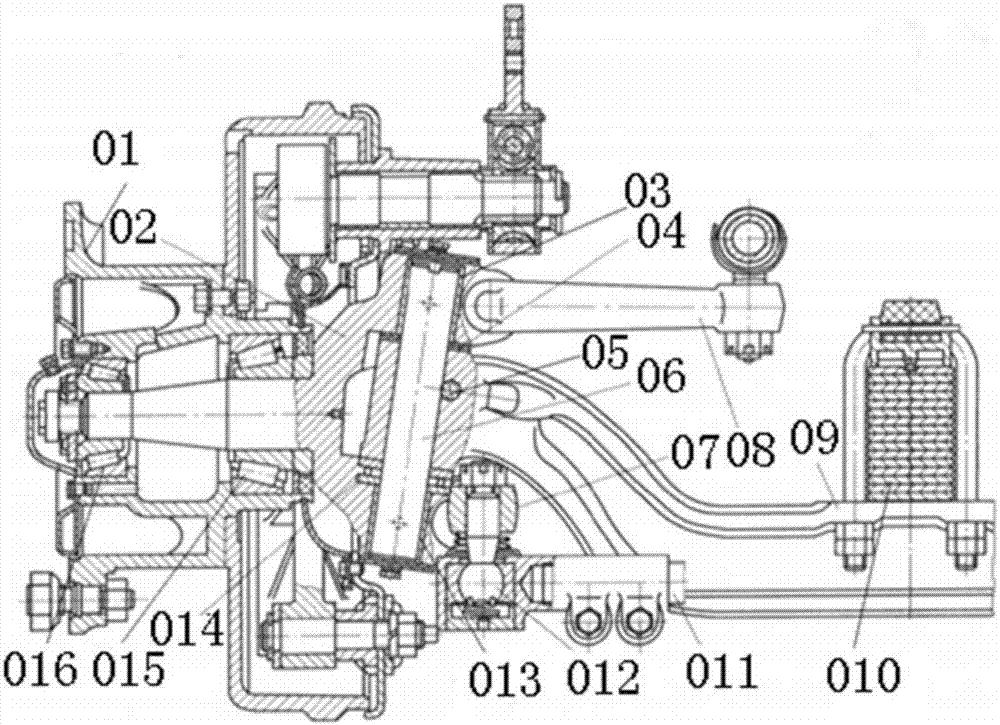
technical field [0001] The invention belongs to the technical field of rolling bearings, in particular to a bidirectional thrust rolling bearing. Background technique [0002] The functions of the bearings in different structures are also different. For example, during the movement of the vehicle, the bearings in the hub unit not only bear the radial force but also bear the axial force, such as figure 1 Inner bearings and outer bearings. The thrust bearing is used between the steering knuckle and the front axle, which only bears the axial force between the steering knuckle and the front axle. [0003] figure 1 It is a schematic diagram of the prior art steering front axle and its related parts, including hub 01, steering knuckle 02, upper bushing 03, adjusting gasket 04, wedge lock pin 05, kingpin 06, steering trapezoidal arm 07, steering knuckle arm 08, Front axle 09, leaf spring 010, steering tie rod 011, ball pin 012, lower bushing 013, thrust bearing 014, inner bearin...

Claims


Application Information

Patent Timeline
IPC IPC(8): F16C19/30F16C33/58
CPCF16C19/305F16C33/583
Inventor 刘守银
Owner ANHUI JIANGHUAI AUTOMOBILE GRP CORP LTD
Why Eureka
Eureka Blog
Learn More