Device and method for monitoring state of pressure plate at outlet of substation

A state monitoring device and outlet pressure plate technology, applied in the field of substations, can solve problems such as inability to monitor, inconvenient transformation, and large degree of transformation, and achieve the effects of avoiding potential safety hazards, intuitive monitoring results, and strong anti-interference ability

Active Publication Date: 2019-08-23
STATE GRID CORP OF CHINA +2
View PDF4 Cites 0 Cited by
  • Summary
  • Abstract
  • Description
  • Claims
  • Application Information

AI Technical Summary

Problems solved by technology

[0004] The above two types of schemes have the following disadvantages: Among them, the first scheme is greatly affected by the light intensity and external light source on the monitoring results, and this scheme can only monitor whether the connecting piece is in the input or exit position, and cannot indicate whether the pressure plate is reliably input. , it is impossible to correctly monitor the situation where the connecting piece is in the closing position but the fixing nut of the connecting piece is not tightened or the breaking point of the connecting piece is not reliably closed; the modification degree of the second scheme is large, the transformation is inconvenient, and the transformation cost is high

Method used


Image

  • Device and method for monitoring state of pressure plate at outlet of substation
  • Device and method for monitoring state of pressure plate at outlet of substation
  • Device and method for monitoring state of pressure plate at outlet of substation

Examples


Embodiment 1

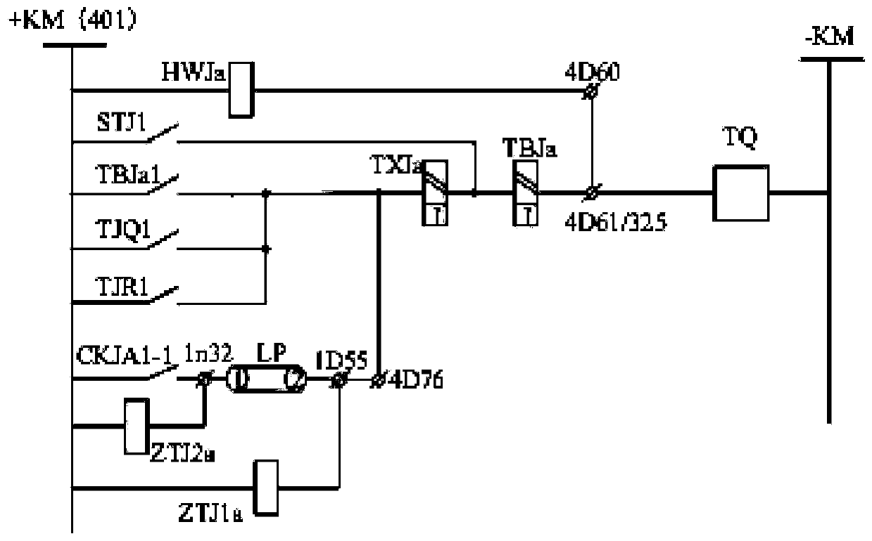
[0038] figure 1 It is a schematic diagram of the status monitoring of the substation outlet pressure plate according to the embodiment of the present invention, such as figure 1 As shown, the embodiment of the present invention provides a substation outlet pressure plate state monitoring device, including: protection action contact CKJA1-1, a first branch and a second branch; the first branch includes a first monitoring relay ZTJ1a; The second branch includes a second monitoring relay ZTJ2a; the protection action contact CKJA1-1 is connected in series with the outlet pressure plate LP to form a third branch; the second branch is connected in parallel with the protection action contact CKJA1-1; The third branch is connected in parallel with the first branch.

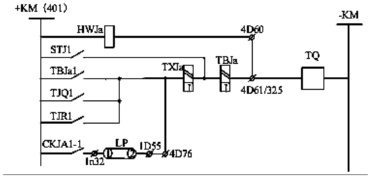
[0039] figure 2 It is the schematic diagram of the A-phase tripping circuit of the CSL-101A line protection device, such as figure 2 As shown, TXJa is the trip signal relay; TBJa is the anti-trip relay; both the trip...

Embodiment 2

[0067] This embodiment is basically the same as Embodiment 1. For the sake of brevity, in the description process of this embodiment, the same technical features as Embodiment 1 will not be described, and only the differences between this embodiment and Embodiment 1 will be described:

[0068] The state of the outlet pressure plate can also be determined according to the states of the protection action contact CKJA1-1, the first monitoring relay ZTJ1a and the second monitoring relay ZTJ2a.

[0069] Table 2 is the logic table 2 for determining the state of the outlet platen, as shown in Table 2:

[0070] Table 2 is the logic table 2 for determining the state of the outlet platen

[0071]

[0072]

[0073]Wherein, if the protection action contact CKJA1-1 is in the cent position, and the first monitoring relay ZTJ1a is excited, and the second monitoring relay ZTJ2a is excited, then it is determined that the outlet pressure plate is in the input state;

[0074] If the prote...

Embodiment 3

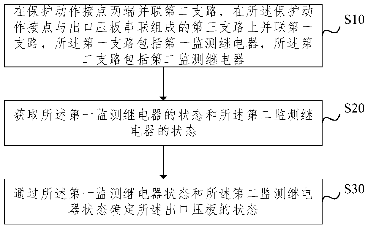
[0080] image 3 It is a flowchart of a method for monitoring the state of a substation outlet pressure plate according to an embodiment of the present invention, as shown in image 3 As shown, the embodiment of the present invention provides a method for monitoring the state of the substation outlet pressure plate, including:

[0081] Step S10, connecting the second branch in parallel at both ends of the protection action contact, and connecting the first branch in parallel on the third branch composed of the protection action contact and the outlet pressure plate in series, the first branch includes the first monitoring relay, so The second branch includes a second monitoring relay;

[0082] Step S20, acquiring the state of the first monitoring relay and the state of the second monitoring relay;

[0083] Step S30, determining the state of the outlet pressing plate according to the state of the first monitoring relay and the state of the second monitoring relay.

[0084] Sp...


PUM


Abstract

The invention provides a state monitoring device and method for an outlet pressure plate of a transformer station. The device comprises a protective motion contact, a first branch and a second branch; the first branch comprises a first monitoring relay; the second branch comprises a second monitoring relay; the protective motion contact connected with the outlet pressure plate in series to form a third branch; the second branch is in parallel connection with the protective motion contact; and the third branch is in parallel connection with the first branch. According to the state monitoring device and method, two monitoring relays are arranged in the circuit, the state of the outlet pressure plate is determined according to states of the monitoring relays, the state of the outlet pressure plate of the transformer station can be monitored automatically, monitoring for the outlet pressure plate is more convenient and reliable, the structure is simple, and the anti-interference capability is high.

Description

technical field [0001] The invention relates to the technical field of substations, in particular to a device and method for monitoring the state of a substation outlet pressure plate. Background technique [0002] With the rapid development and wide application of computer, network communication and database technology, substation automation has developed rapidly, thus greatly improving the efficiency and safety of power grid operation. Relay protection is an important part of the substation automation system, and the degree of automation of the device itself has an important impact on the automation level of the substation. [0003] In the existing technology, the relay protection outlet pressure plate still adopts manual on-site verification for state detection, the automation and reliability level is low, and there is a hidden danger of unnecessary accidents caused by incorrect switching of the outlet pressure plate. There are mainly two types of research schemes for th...

Claims


Application Information

Patent Timeline
Patent Type & Authority Patents(China)
IPC IPC(8): H02J13/00
Inventor 徐浩欧阳帆梁文武张磊李辉敖非朱维钧刘宇臧欣许立强刘海峰陈宏
Owner STATE GRID CORP OF CHINA
Why Eureka
Try Eureka