Small circular hole cutting assisting device

An auxiliary device and round hole technology, applied in welding equipment, laser welding equipment, metal processing equipment, etc., can solve the problems of few sides, affecting product quality, low repeat positioning accuracy, etc., and achieve the effect of precise shape

Active Publication Date: 2017-08-25
平湖凯隆新材料科技有限公司
View PDF5 Cites 11 Cited by
  • Summary
  • Abstract
  • Description
  • Claims
  • Application Information

AI Technical Summary

Problems solved by technology

[0012] However, there is such a problem when using a laser cutting robot to cut a metal plate, especially in the field of automobile manufacturing, it is often necessary to cut small circular holes with a small diameter on the metal plate, and the use of robot programming can also make the laser cut along a circle , the computer of the robot system determines the circular trajectory through equation calculation, takes a limited number of points within the value range of the equation to calculate the coordinates of multiple points, and connects the coordinates of multiple points in turn to form an approximate circle, so The drawn circle is treated as a polygon. When the diameter of the circular hole is large, such as greater than 10mm, the number of vertices of the polygon is large and it looks round. But when the diameter of the circular hole is small, such as less than 3mm, The number of sides of a polygon is often small, and the small round hole cut out can be seen by the naked eye not as a circle, but a polygon, such as an octagon or a hexagon, which affects the quality of the product
Furthermore, when the size of the workpiece is large, the model of the robot is increased, its accuracy tends to be lower, and the repeat positioning accuracy is also often lower, especially the positioning accuracy in motion is lower. If the robot's arm is fixed, Repeat positioning accuracy is relatively high

Method used


Image

  • Small circular hole cutting assisting device
  • Small circular hole cutting assisting device
  • Small circular hole cutting assisting device

Examples


Embodiment

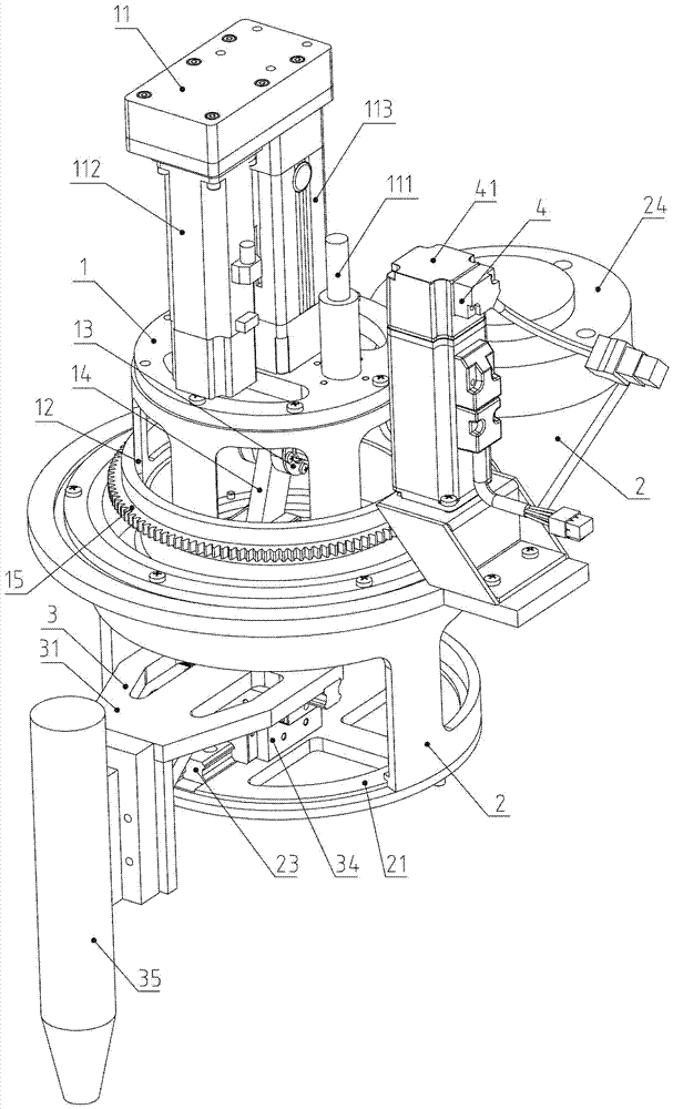
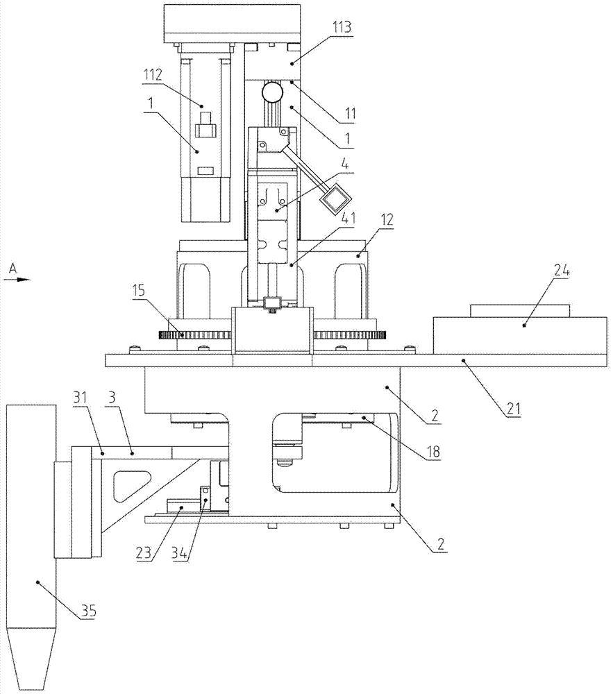
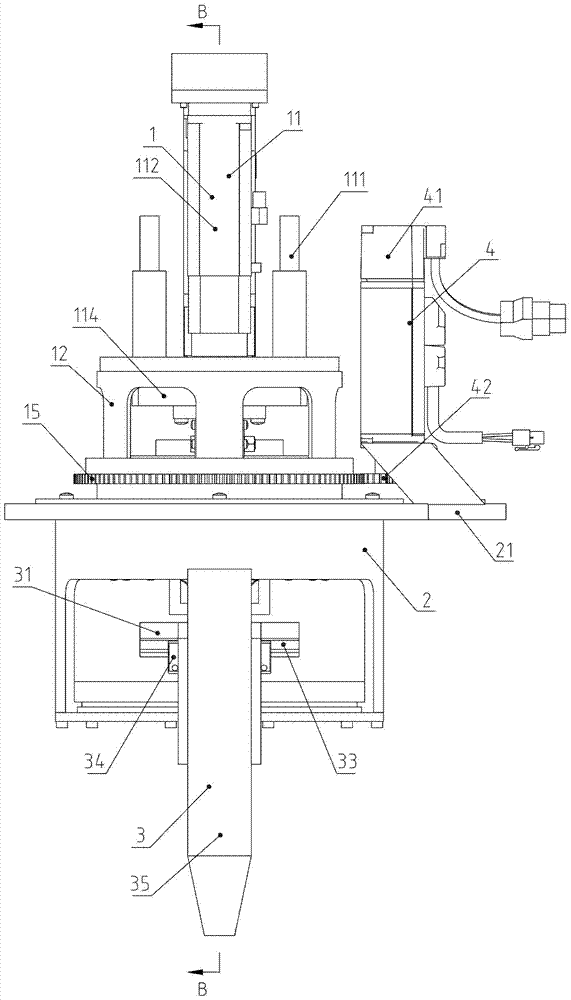
[0045] Example: see Figure 1 to Figure 10 .

[0046] An auxiliary device for cutting small round holes, comprising a rotary assembly 1, a bracket assembly 2, a laser assembly 3 and a rotary drive device 4;

[0047] The rotary assembly 1 includes a guiding electric cylinder 11, a rotating bracket 12, a connecting rod 14, a large gear 15, a linear slider 17 and a linear guide rail 18, and the guiding electric cylinder 11 includes a guide rod-guide sleeve combination 111, an electric cylinder servo motor 112 , the electric cylinder body 113 and the electric cylinder rod, the end of the electric cylinder rod is fixed with a cylinder rod end plate 114, the guide sleeve is fixedly connected with the electric cylinder body 113, the guide rod is fixedly connected with the cylinder rod end plate 114, the electric cylinder servo motor 112 and the electric cylinder The transmission mechanism in the cylinder block 113 is connected. When the electric cylinder servo motor 112 is energized...


PUM


Abstract

The invention belongs to the technical field of industrial automation production equipment, and relates to a small circular hole cutting assisting device. A rotating assembly comprises a guide electric cylinder, a rotating support, a connecting rod, a linear sliding block and a first linear guide rail, an annular V-shaped rail is arranged on the rotating support, the guide electric cylinder stretches out and retracts back to drive the linear sliding block to transversely move in the vertical direction through the connecting rod, and the distance between a deep groove ball bearing center line on the linear sliding block and the rotating center line of the rotating support is R; and a laser assembly comprises a laser support, a third linear guide rail and a cross-shaped sliding block, the laser support and the linear sliding block form a rotating pair through a deep groove ball bearing, two sliding grooves are formed in the cross-shaped sliding block and form a linear guide rail pair with the third linear guide rail and a second linear guide rail, and the laser assembly transversely moves relative to the support assembly along the third linear guide rail and / or the second linear guide rail. By means of the small circular hole cutting assisting device, circular holes with small diameters can be cut off, the shapes of the holes are accurate, and obstructing of other work doing by a laser cutting robot is avoided.

Description

technical field [0001] The invention belongs to the technical field of industrial automatic production equipment, and relates to an auxiliary device for metal intelligent cutting equipment, in particular to an auxiliary device for cutting small round holes. Background technique [0002] Laser cutting technology uses a focused high-power-density laser beam to irradiate the workpiece, so that the irradiated material is rapidly melted, vaporized, ablated or reached the ignition point, and at the same time, the molten material is blown away by the high-speed airflow coaxial with the beam, so as to achieve the workpiece cut open. Laser cutting is one of the thermal cutting methods. Laser cutting can be divided into four categories: laser vaporization cutting, laser melting cutting, laser oxygen cutting, and laser scribing and controlled fracture. [0003] Laser cutting has many advantages over other thermal cutting methods. [0004] 1) Fast cutting speed. Using a laser with a...

Claims


Application Information

Patent Timeline
Patent Type & Authority Applications(China)
IPC IPC(8): B23K26/382
CPCB23K26/389
Inventor 李伦锦其他发明人请求不公开姓名
Owner 平湖凯隆新材料科技有限公司
Why Eureka
Try Eureka