Eureka AIR delivers breakthrough ideas for toughest innovation challenges, trusted by R&D personnel around the world.

Single-cylinder-driven rotary band-type brake mechanism

A transmission mechanism and single-cylinder technology, applied in the field of rotary brake mechanism, can solve the problems of high wear rate of the rotary brake nut, prolong the service life, reduce the cost of the machine, etc., and achieve the effect of low cost, long service life and simple processing

Pending Publication Date: 2017-08-25
NINGBO DOUSH HYDRAULIC
View PDF0 Cites 1 Cited by
  • Summary
  • Abstract
  • Description
  • Claims
  • Application Information

AI Technical Summary

Problems solved by technology

[0002] Since the mold clamping mechanism of the two-plate plastic injection molding machine has no crankshaft and connecting rod mechanism, the movement pairs of the mechanism are greatly reduced. Due to the reduction of mechanical vulnerable parts, the service life of the machine is greatly prolonged. In addition, the mold clamping mechanism of the two-plate plastic injection molding The crankshaft connecting rod mold clamping mechanism lacks a template, which greatly reduces the cost of the machine for medium and large machines, because the movable module is separated from the tie rod when the mold is opened, and the movable template passes through the tie rod when the mold is clamped under high pressure. One mechanism is locked, and the two-platen plastic injection molding machine of this mechanism is called a brake mechanism or a turn-brake mechanism. According to the prior art, a two-platen injection molding machine turn-gate mechanism is disclosed on the website of the State Intellectual Property Office. The driving device drives four turnstile engaging parts at the same time, and the turning turnstile engaging parts are connected synchronously through linkage links, mainly through the driving device to drive one turngate engaging part to rotate, and then link the remaining three turnstile parts through the connecting rod, so that The turnstile nut is always exposed outside, and dust is easy to enter it. The wear rate of the turnstile nut is high and the service life is short. At the same time, it is necessary to ensure the machining accuracy of the entire turnstile meshing parts. The processing is troublesome, the cost is high, and the precision requirements are high.

Method used


Image

  • Single-cylinder-driven rotary band-type brake mechanism
  • Single-cylinder-driven rotary band-type brake mechanism
  • Single-cylinder-driven rotary band-type brake mechanism

Examples


Embodiment Construction

[0021] The present invention will be further described below in conjunction with the accompanying drawings and specific embodiments.

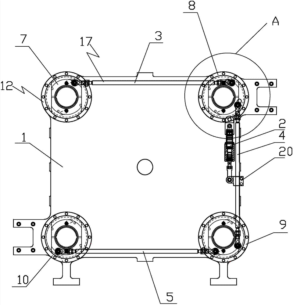
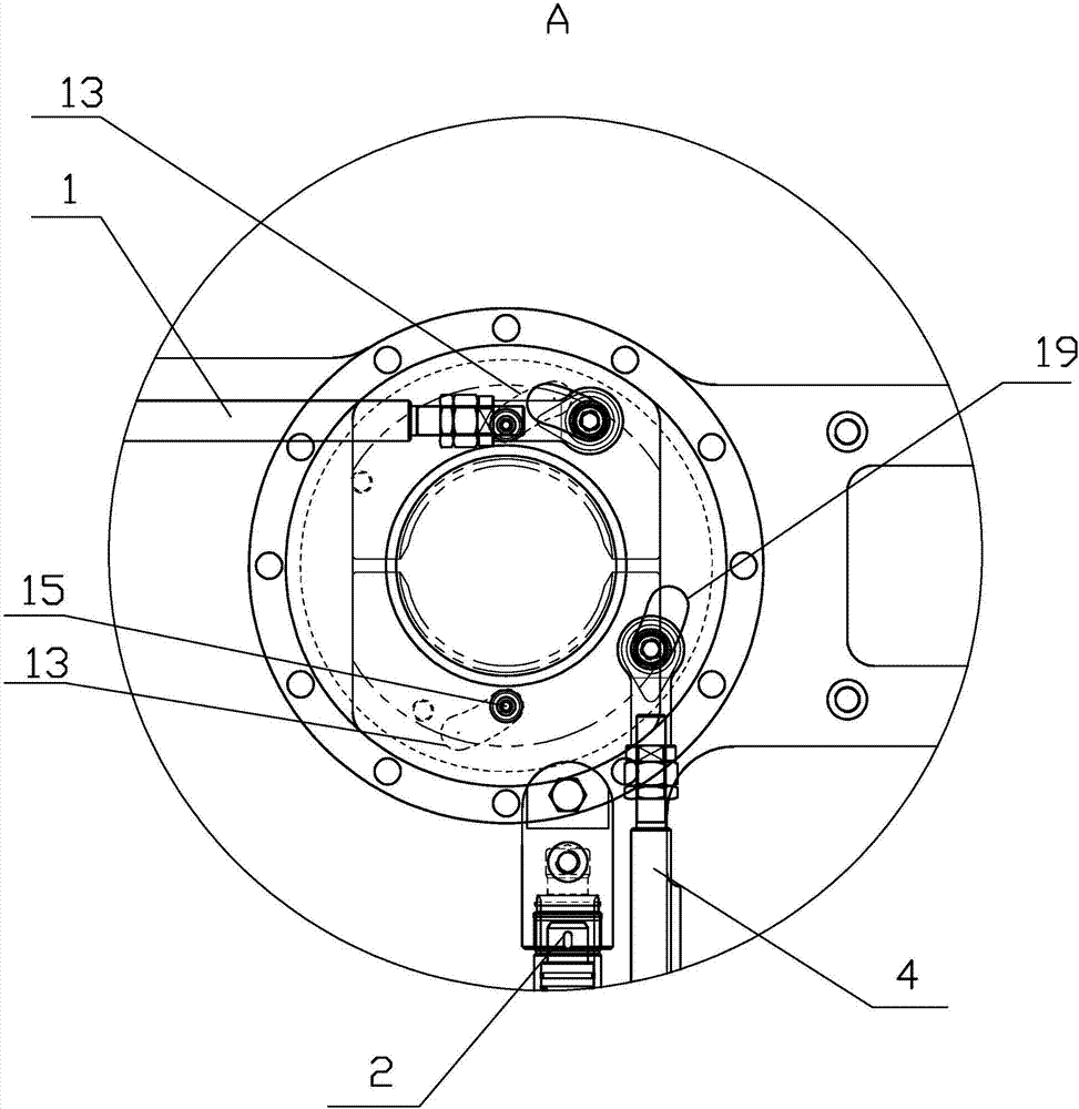
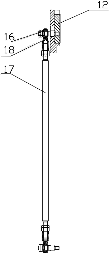
[0022] As shown in the figure, the present invention provides a rotary brake mechanism driven by a single cylinder, which includes a movable template 1, a brake cylinder 2, a connecting rod 17, an engagement nut 6 and a turntable 12, and the connecting rod 17 includes a first connecting rod. Rod 3, second connecting rod 4 and third connecting rod 5, said turntable 12 includes first turntable 7, second turntable 8, third turntable 9 and fourth turntable 10, said first turntable 7, second turntable The second turntable 8, the third turntable 9 and the fourth turntable 10 are arranged in sequence in a rectangular distribution, the first connecting rod 3 is located between the first turntable 7 and the second turntable 8, and the second link 4 is located between the first turntable 7 and the second turntable 8. Between the second turntable 8 and th...


PUM


Abstract

The invention discloses a single-cylinder-driven rotary band-type brake mechanism comprising a movable template, a band-type brake oil cylinder, a connecting rod, a holding nut and a rotary disc. The connecting rod comprises a first connecting rod, a second connecting rod and a third connecting rod. The rotary disc comprises a first rotary disc, a second rotary disc, a third rotary disc and a fourth rotary disc which are arranged sequentially and distributed in a rectangular shape. The first connecting rod is located between the first rotary disc and the second rotary disc. The second connecting rod is located between the second rotary disc and the third rotary disc. The third connecting rod is located between the third rotary disc and the fourth rotary disc. End covers are fixed to the movable template. The rotary discs are arranged on the end covers correspondingly and rotationally in a matched mode. The holding nut is located below the rotary discs and comprises at least two arc-shaped blocks. The single-cylinder-driven rotary band-type brake mechanism provided by the invention is long in service life, low in cost, simple to machine and low in precision requirement.

Description

technical field [0001] The invention relates to a mechanism of a two-platen injection molding machine, in particular to a rotary brake mechanism driven by a single cylinder. Background technique [0002] Since the mold clamping mechanism of the two-plate plastic injection molding machine has no crankshaft and connecting rod mechanism, the movement pairs of the mechanism are greatly reduced. Due to the reduction of mechanical vulnerable parts, the service life of the machine is greatly prolonged. In addition, the mold clamping mechanism of the two-plate plastic injection molding The crankshaft connecting rod mold clamping mechanism lacks a template, which greatly reduces the cost of the machine for medium and large machines, because the movable module is separated from the tie rod when the mold is opened, and the movable template passes through the tie rod when the mold is clamped under high pressure. One mechanism is locked, and the two-platen plastic injection molding machi...

Claims


Application Information

Patent Timeline
Patent Type & Authority Applications(China)
IPC IPC(8): B29C45/66
CPCB29C45/66B29C2045/664
Inventor 周贤辉陈学琛杨云毅
Owner NINGBO DOUSH HYDRAULIC
Why Eureka
Eureka Blog
Learn More