Lateral rigidity enhancing structure of open section of subway entrance

A technology of lateral rigidity and structural reinforcement, which is applied in underwater structures, infrastructure engineering, construction, etc., and can solve problems such as poor waterproofing at special-shaped interfaces, increased scale and cost of entrances and exits, and large stress on the main side wall. , to achieve clear design theory, meet the anti-floating requirements, and increase the horizontal bending stiffness

Pending Publication Date: 2017-08-25
CHINA RAILWAY SIYUAN SURVEY & DESIGN GRP
View PDF9 Cites 2 Cited by
  • Summary
  • Abstract
  • Description
  • Claims
  • Application Information

AI Technical Summary

Problems solved by technology

For the problem of anti-floating, the current common practice is that the crown beam is 200mm-300mm wider than the surrounding protection piles, and a groove is set during the construction of the main side wall, and the surrounding structure is used to participate in anti-floating. However, because the steel bars in the groove are not easy to bind, Moreover, the waterproofing at the special-shaped interface is not easy to deal with, which often increases the difficulty of construction and affects the construction period; in view of the problem of large force on the main side wall, generally increase the thickness of the main side wall of the cantilever or increase the reinforcement at the junction of the main side wall and the bottom plate, so that Increase the scale and cost of entrances and exits

Method used


Image

  • Lateral rigidity enhancing structure of open section of subway entrance
  • Lateral rigidity enhancing structure of open section of subway entrance

Examples


Embodiment Construction

[0019] In order to make the object, technical solution and advantages of the present invention clearer, the present invention will be further described in detail below in conjunction with the accompanying drawings and embodiments. It should be understood that the specific embodiments described here are only used to explain the present invention, not to limit the present invention. In addition, the technical features involved in the various embodiments of the present invention described below can be combined with each other as long as they do not constitute a conflict with each other.

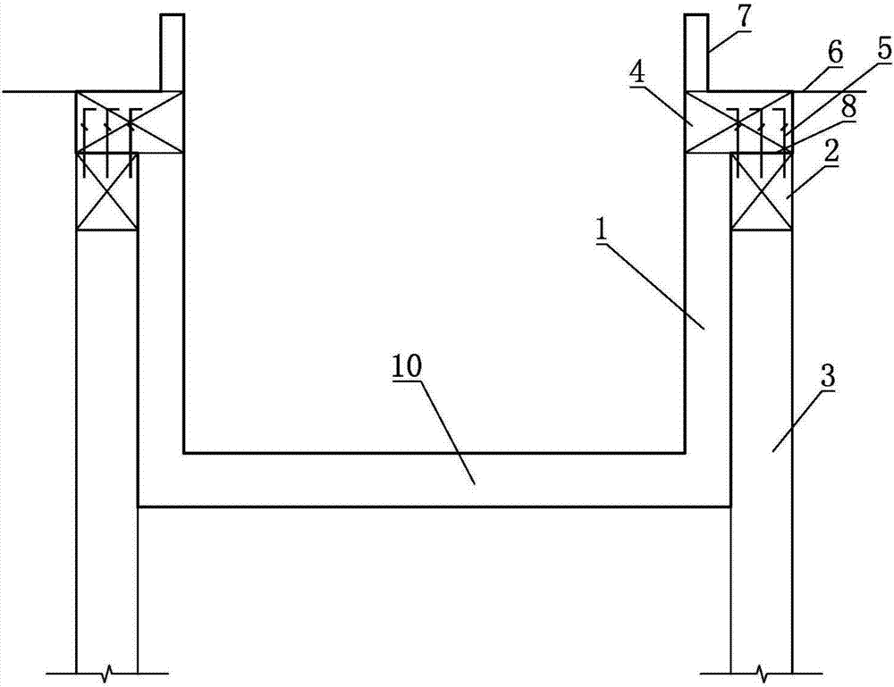
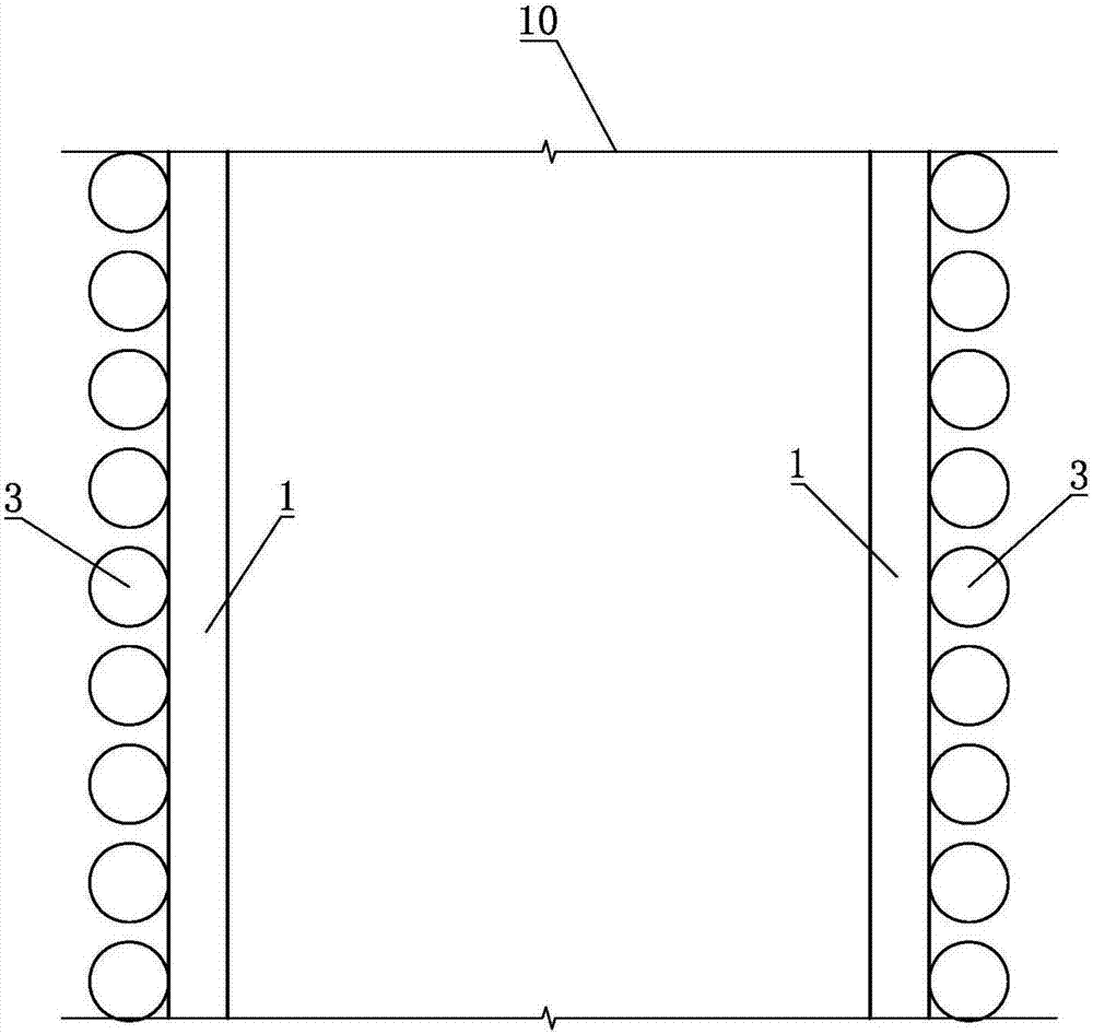
[0020] refer to figure 1 , figure 2 , a lateral rigidity enhancement structure for the open section of the subway entrance and exit, including a bottom plate 10, two main side walls 1, crown beams 2, enclosure piles 3, ring beams 4 and inserting ribs 5, all of which are located under the planned ground 6 , the planned ground 6 is provided with a ground side wall 7, wherein,

[0021] The two ...


PUM


Abstract

The invention belongs to the field of deep foundation pit engineering, and discloses a lateral rigidity enhancing structure of an open section of a subway entrance. The lateral rigidity enhancing structure comprises a bottom slab, two main body side walls, top beams, two rows of fender posts, ring beams and joint bars. The two main body side walls are arranged on the bottom slab, and a U-shaped structure is formed by the two main body side walls and the bottom slab jointly. The tops of each row of fender posts bear the corresponding top beam, and the top of each top beam is flush with the top end face of the corresponding main body side wall of the U-shaped structure. Each main body side wall and the adjacent top beam jointly form a ring beam bearing structure. Each ring beam bearing structure bears the corresponding ring beam. The top beams and the ring beams are connected through the multiple joint bars. The lower ends of the joints bars are anchored into the top beams, and the upper ends of the joint bars stretch into the ring beams. The lateral rigidity enhancing structure has the advantages that construction is convenient and fast, the amount of steel bars is small, investment is reduced, and structure safety and the waterproof effect are guaranteed, and has great application prospects in the field of deep foundation pit engineering including subways.

Description

technical field [0001] The invention belongs to the field of deep foundation pit engineering, and more specifically relates to an open section structure of a subway entrance and exit. Background technique [0002] In the open section of the subway entrance and exit, in order to meet the requirements of the clear height of the building, a large opening is set on the roof (generally more than 12m along the entrance and exit direction). The structure here is a U-shaped structure with only the bottom plate and the main side wall. Under the high anti-floating water level, the open section of the entrance and exit needs to use the enclosure structure to participate in the anti-floating; on the other hand, because the main side wall is a cantilever structure fixed on the lower side, under the action of lateral water and soil pressure, the force of the main side wall larger. For the problem of anti-floating, the current common practice is that the crown beam is 200mm-300mm wider th...

Claims


Application Information

Patent Timeline
Patent Type & Authority Applications(China)
IPC IPC(8): E02D29/045E02D31/00
CPCE02D29/045E02D31/00
Inventor 陈辉万勇王永伟薛城付先进丁录董李胜强董俊
Owner CHINA RAILWAY SIYUAN SURVEY & DESIGN GRP
Why Eureka
Try Eureka