Mixing equipment for cosmetic production

A technology for stirring equipment and cosmetics, which is applied in the direction of mixer accessories, mixers with rotating stirring devices, chemical instruments and methods, etc., which can solve the problems of wasting production raw materials, uneven mixing of raw materials, and low efficiency of equipment, so as to reduce work Time, convenient and full mixing, convenient mixing effect

Inactive Publication Date: 2017-08-29
泉州惠安长圣生物科技有限公司
View PDF5 Cites 7 Cited by
  • Summary
  • Abstract
  • Description
  • Claims
  • Application Information

AI Technical Summary

Problems solved by technology

[0003] In the production process, various raw materials are usually directly put into the mixing tank in piles, which causes the mixing equipment to spend more time to fully mix these piles of raw materials, which leads to low working efficiency of the equipment, not only In this way, when the existing stirring equipment is working, because the raw materials rotate along the central axis of the stirring shaft and are affected by the centrifugal force, they usually splash and adsorb on the inner wall of the stirring tank, and the stirring paddles cannot touch these sticky materials on the stirring shaft. Raw materials will not only cause uneven mixing of raw materials, but also waste production raw materials

Method used


Image

  • Mixing equipment for cosmetic production
  • Mixing equipment for cosmetic production
  • Mixing equipment for cosmetic production

Examples


Embodiment Construction

[0031] The present invention is described in further detail now in conjunction with accompanying drawing. These drawings are all simplified schematic diagrams, which only illustrate the basic structure of the present invention in a schematic manner, so they only show the configurations related to the present invention.

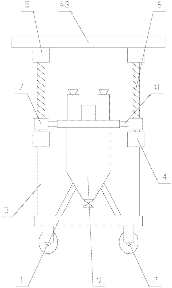
[0032] like Figure 1-Figure 7 As shown, a stirring device for cosmetics production includes a base 1, a stirring mechanism 9 and two pillars 3, and the two pillars 3 are respectively arranged on both sides of the stirring mechanism 9, and the bottom ends of the pillars 3 are fixed on base 1;

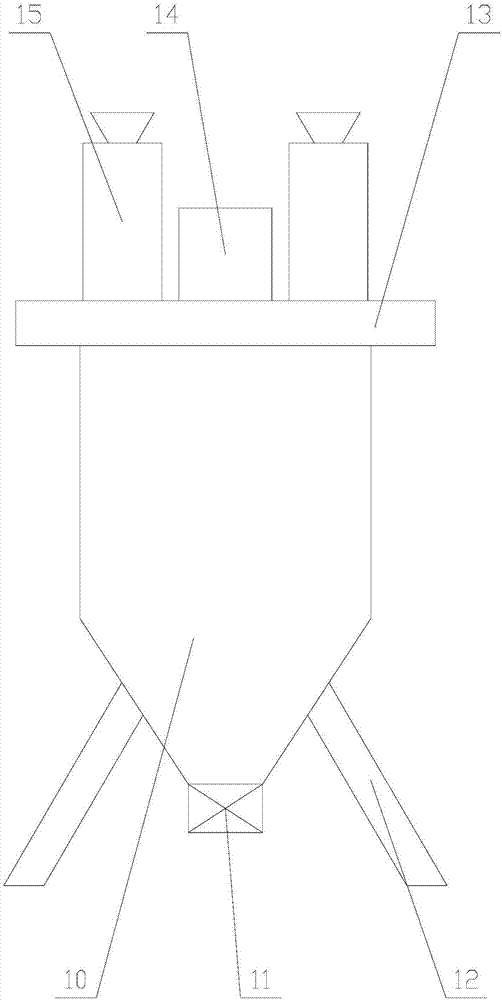
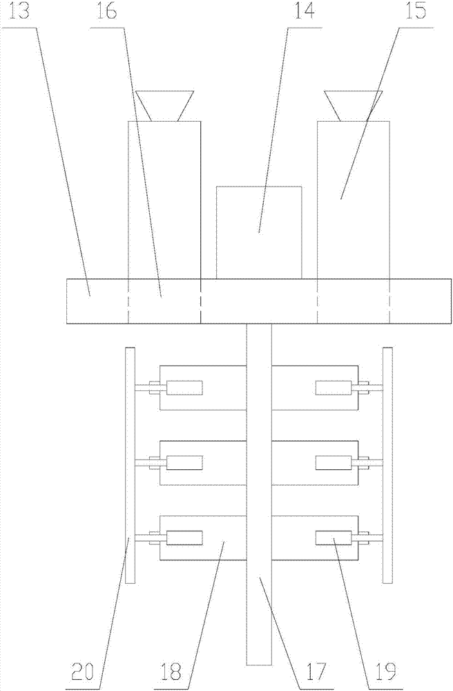
[0033] The stirring mechanism 10 comprises a stirring tank 10, a pot cover 13, a stirring assembly, a second drive motor 14, two feeding units 15 and several legs 12, and the stirring tank 10 is fixed on the base 1 by the legs 12, the The bottom end of the mixing tank 10 is provided with a discharge valve 11, the pot cover 13 is arranged on the top of the mixing tank ...


PUM


Abstract

The invention relates to mixing equipment for cosmetic production. The mixing equipment comprises a mixing mechanism, wherein the mixing mechanism comprises a mixing assembly and two feeding units, the mixing assembly consists of a second driving shaft and mixing units arranged on two sides of the second driving shaft, each mixing unit comprises a scraper plate and a plurality of mixing paddles, telescopic units are arranged on two sides of each mixing paddle; each telescopic unit consists of a sleeve, a sliding rod, a first coil and a second coil; each feeding unit consists of a shell; a storage box, a first guide pipe, a support rod and an orientation unit are arranged in the shell. According to the mixing equipment for cosmetic production, the angle of a nozzle can be always adjusted through the orientation unit, and raw materials are dispersed and distributed on a mixing cylinder, so that the raw materials can be thoroughly mixed conveniently by the equipment, the working time can be shortened, and the mixing efficiency can be improved; furthermore, the scraper plate is contacted with the inner wall of the mixing cylinder through the telescopic units, so as to scrape the raw materials adhered on the edges and lead the scraped raw materials to be mixed, and therefore, the loss of the raw materials can be decreased, and the practicability of the equipment can be increased.

Description

technical field [0001] The invention relates to the field of cosmetic production equipment, in particular to a stirring equipment for cosmetic production. Background technique [0002] Mixer is a kind of mechanical equipment commonly used in cosmetics production. In the process of cosmetics production and processing, it is often necessary to stir different materials. The mixer uses a drive motor to rotate the drive shaft with the descending plate blade in the mixing cylinder, so that The various raw materials inside the container come into contact to achieve a mixing effect, which facilitates the production of cosmetics. [0003] In the production process, various raw materials are usually directly put into the mixing tank in piles, which causes the mixing equipment to spend more time to fully mix these piles of raw materials, which leads to low working efficiency of the equipment, not only In this way, when the existing stirring equipment is working, because the raw materi...

Claims


Application Information

Patent Timeline
Patent Type & Authority Applications(China)
IPC IPC(8): B01F13/00B01F15/00B01F15/02B01F7/18B01F7/00
CPCB01F27/17B01F27/90B01F33/501B01F35/123B01F35/42B01F35/7179B01F2101/21
Inventor 吴丽清
Owner 泉州惠安长圣生物科技有限公司
Why Eureka
Try Eureka