Full-station composite cutter bar for processing petroleum pipe threads

A full-station, compound knife technology, applied in the direction of thread cutting tools, metal processing equipment, tool holders, etc., can solve the problems of increased thread surface roughness, reduced service life of tool holders, and impact on processing efficiency, so as to reduce the use of cost, prolong service life, and improve economic efficiency

Inactive Publication Date: 2017-08-29
KUNSHAN HIECISE PRECISION TOOL
View PDF0 Cites 0 Cited by
  • Summary
  • Abstract
  • Description
  • Claims
  • Application Information

AI Technical Summary

Problems solved by technology

[0002] At present, oil tubing and casing thread processing usually use separate tools to complete multiple processing steps such as flat end face, outer circle turning, thread processing, deburring, internal chamfering, etc. Every time a processing step is completed, the tool must be changed , frequent tool change actions seriously affect the processing efficiency and increase the failure rate of the rotary tool holder. When processing threads, the internal thread cutter bar used by the CNC lathe can only be equipped with one kind of tool, that is, the thread comb cutter. Since the tool bar itself does not have a broken Chip device, so that during the processing, iron filings are entangled on the tool holder, causing the surface roughness of the thread to increase or even damage the thread, and the service life of the tool holder is reduced

Method used


Image

  • Full-station composite cutter bar for processing petroleum pipe threads
  • Full-station composite cutter bar for processing petroleum pipe threads
  • Full-station composite cutter bar for processing petroleum pipe threads

Examples


Embodiment

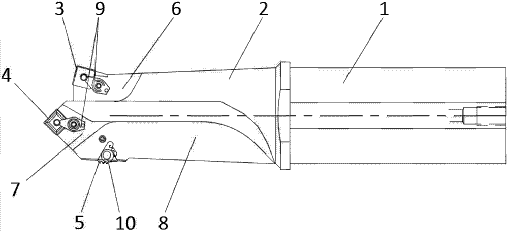
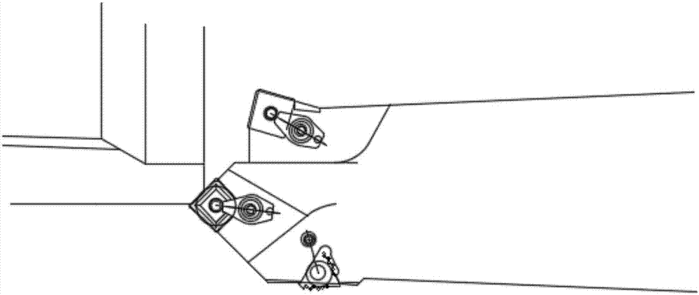
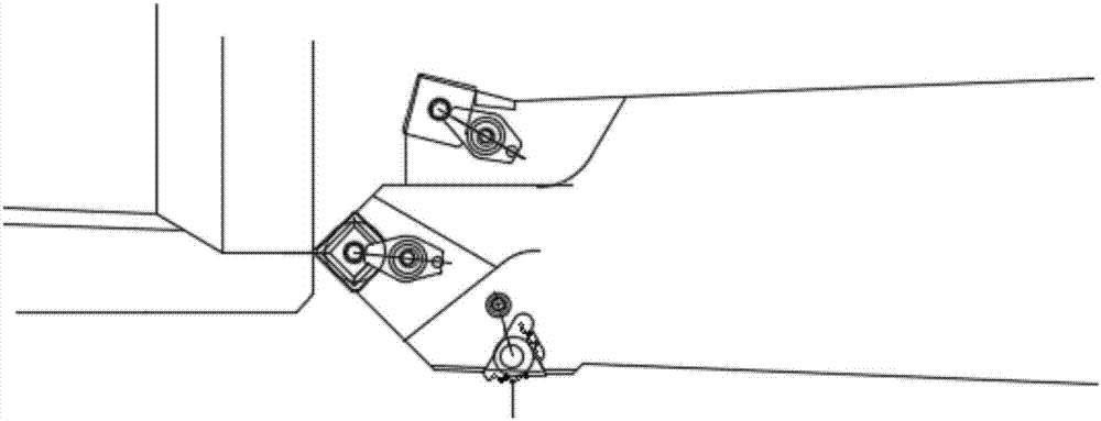
[0016] Such as figure 1 As shown, this embodiment provides a full-station composite tool holder for processing oil pipe threads, which includes a tool holder body 1; a blade connecting portion 2 is provided at the front end of the cutter rod body 1; The upper side of the upper side is provided with a boring blade 3, the front side is provided with a chamfering blade 4, and the lower side is provided with a threaded blade 5; Matching installation plane; the blade connecting portion 2 between the boring blade 3 and the tool holder body 1 is provided with a boring chip removal guide surface 6; the chamfering blade 4 and the blade between the tool holder body 1 The connecting part 2 is provided with a chamfering chip removal guide surface 7; the blade connection part 2 between the threaded insert 5 and the tool holder body 1 is provided with a threaded chip removal guide surface 6; the boring blade 3, chamfering The blades 4 and threaded blades 5 are distributed in a triangular s...


PUM


Abstract

The invention relates to a full-station composite cutter bar for processing petroleum pipe threads. The full-station composite cutter bar comprises a cutter bar body, and a blade connecting part is arranged at the front end of the cutter bar body; a boring blade is arranged on the upper side of the front end of the blade connecting part; a chamfering blade is arranged on the front side of the front end of the blade connecting part; a threading blade is arranged on the lower side of the front end of the blade connecting part; a mounting plane matched with the boring blade, the chamfering blade and the threading blade is arranged on the blade connecting part; a boring chip removal guide surface is arranged in the position, between the boring blade and the cutter bar body, on the blade connecting part; a chamfering chip removal guide surface is arranged in the position, between the chamfering blade and the cutter bar body, on the blade connecting part; and a threading chip removal guide surface is arranged in the position, between the threading blade and the cutter bar body, on the blade connecting part. According to the full-station composite cutter bar for processing the petroleum pipe threads, end face chamfer turning, excircle turning, bored hole burr removal and thread turning procedures can be carried out at the same time, the blade does not need to be changed halfway, chips can be quickly discharged, processing efficiency can be improved, the risk that a rotating knife rest breaks down is reduced, service life of a cutter is prolonged, utilization cost of the cutter is reduced, and economic benefits are increased.

Description

technical field [0001] The invention relates to the field of oil pipe processing, in particular to an all-station composite cutter bar for processing oil pipe threads. Background technique [0002] At present, oil tubing and casing thread processing usually use separate tools to complete multiple processing steps such as flat end face, outer circle turning, thread processing, deburring, internal chamfering, etc. Every time a processing step is completed, the tool must be changed , frequent tool change actions seriously affect the processing efficiency and increase the failure rate of the rotary tool holder. When processing threads, the internal thread cutter bar used by the CNC lathe can only be equipped with one kind of tool, that is, the thread comb cutter. Since the tool bar itself does not have a broken Chip device, so that during the processing, iron filings are entangled on the tool holder, resulting in increased thread surface roughness and even damage to the thread, ...

Claims


Application Information

Patent Timeline
Patent Type & Authority Applications(China)
IPC IPC(8): B23G5/20B23B29/24
CPCB23G5/20B23B29/24
Inventor 王军伟
Owner KUNSHAN HIECISE PRECISION TOOL
Why Eureka
Try Eureka