Lateral welding clamp for laser welding

A laser welding and welding clip technology, applied in laser welding equipment, welding equipment, manufacturing tools, etc., can solve problems such as inability to meet work requirements, slow welding speed, welding dislocation, etc., to improve equipment automation and production efficiency, improve Accurate and fast alignment effect

Active Publication Date: 2017-08-29
48TH RES INST OF CHINA ELECTRONICS TECH GROUP CORP
View PDF8 Cites 6 Cited by
  • Summary
  • Abstract
  • Description
  • Claims
  • Application Information

AI Technical Summary

Problems solved by technology

[0003] At present, manual operation is generally used for side welding, and each side of the required weldment is welded separately. The welding ...

Method used


Image

  • Lateral welding clamp for laser welding
  • Lateral welding clamp for laser welding

Examples


Embodiment Construction

[0018] The present invention will be described in further detail below in conjunction with the accompanying drawings and specific embodiments.

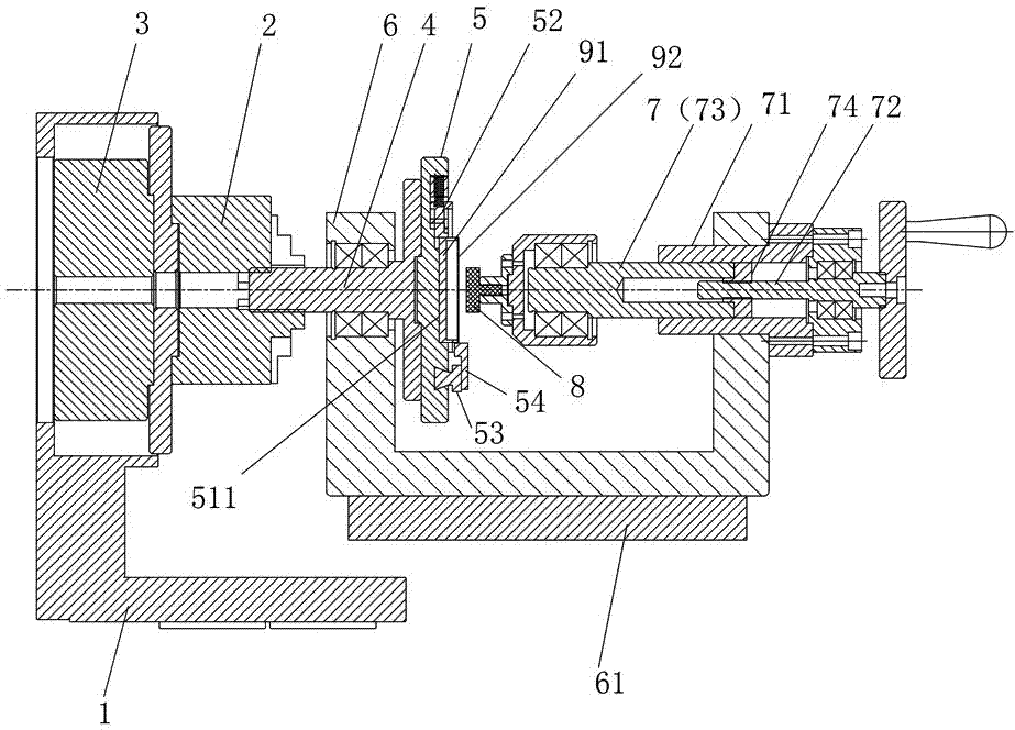
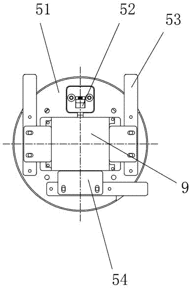
[0019] Such as figure 1 and figure 2 As shown, the side welding fixture for laser welding in this embodiment includes a base 1, a chuck 2, a chuck rotation driver 3, a mounting seat 4, a workpiece fixture 5, a connecting bracket 6, a telescopic rod assembly 7 and a Tighten the thimble 8 of the workpiece 9, the chuck rotation driver 3 is installed on the base 1 and connected with the chuck 2, the mounting seat 4 is clamped in the chuck 2, the workpiece fixture 5 is installed on the mounting seat 4, and the connecting bracket 6 One side is rotatably matched with the mounting base 4 , the telescopic rod assembly 7 is mounted on the other side of the connecting bracket 6 , and the thimble 8 is rotatably mounted on the telescopic rod assembly 7 and arranged toward the workpiece fixture 5 .

[0020] The side welding jig for laser welding...


PUM


Abstract

The invention discloses a lateral welding clamp for laser welding. The lateral welding clamp for laser welding comprises a base, a chuck, a chuck rotation driving part, an installation seat, a work clamp, a connection support, a telescopic rod assembly and an abutting piece used for tightly abutting against a workpiece. The chuck rotation driving part is installed on the base and connected with the chuck. The installation seat is clamped into the chuck. The workpiece clamp is installed on the installation seat. One side of the connection support is in rotating fit with the installation seat. The telescopic rod assembly is installed on the other side of the connection support. The abutting pin is rotationally installed on the telescopic rod assembly and faces the workpiece clamp. The lateral welding clamp for laser welding has the advantages of being high in automation degree, completing welding of all the lateral faces in a one-off manner after clamping, achieving accurate alignment and being high in production efficiency.

Description

technical field [0001] The invention relates to laser welding equipment, in particular to a side welding fixture for laser welding. Background technique [0002] With the development of various laser generators towards high power, portability and economy, laser welding is in line with technological developments such as high quality, low consumption, high efficiency, cleanliness, small joint deformation, and flexible operation due to high energy concentration and small heat-affected zone. direction, and the laser beam has the advantage of being able to weld in the atmosphere. It can not only perform deep penetration welding on large components, but also perform precision welding on micro-shaped parts. Its application prospects are very broad. In particular, laser welding is used in the field of micro-assembly. In an airtight or protective atmosphere, the thick film or thin film integrated circuit is packaged into the airtight container of the cover plate and the shell, which ...

Claims


Application Information

Patent Timeline
IPC IPC(8): B23K26/70B23K26/21
CPCB23K26/21B23K26/702
Inventor 陈庆广邓斌王学仕周水清赵瓛何永平
Owner 48TH RES INST OF CHINA ELECTRONICS TECH GROUP CORP
Why Eureka
Try Eureka