Hydrostatic pressure sealing type crack packer

A hydrostatic pressure and packer technology, applied in the directions of sealing/packing, wellbore/well components, earth-moving drilling, etc., can solve the problems of high operation requirements, troublesome decompression, easy to set in advance, etc., to improve sandblasting. Efficient, easy to decompress, easy to use

Inactive Publication Date: 2017-08-29
盐城市畅海精密机械有限公司
View PDF1 Cites 2 Cited by
  • Summary
  • Abstract
  • Description
  • Claims
  • Application Information

AI Technical Summary

Problems solved by technology

The expandable packer sets the packer mainly through the pressure difference inside and outside the pipe string. The disadvantage is that in order to maintain the set state of the packer in the pipe string, ground facilities need to be pressurized to maintain it. It caused early setting, and the use of throttling sand blaster to increase the pressure of the inner pipe string reduced the working efficiency of the pipe string
The mechanical packer is stable in setting, and the slip structure is fixed on the well wall without sliding, but it is troublesome to decompress, and the deposition of sand particles in the well after setting is easy to unsealing failure, which requires relatively high operation requirements and low capacity error
Our company has applied for two patents before, the patent number is: 201420129567.4, the name: a new type of fracturing packer, the packer has no anti-setting device, and it is easy to set in advance; the application number is: 20151029178.2, non-throttle seat Seal the Y344 fracturing packer, its setting provides and maintains pressure in the construction pipe string through ground equipment, and requires the operator to fine-tune the spring according to the depth of the bottom layer, which requires higher requirements for the operator
In order to solve the above problems, the scientific and technological personnel of scientific research institutes continue to research and explore, and develop new fracturing packers. Although some progress has been made in technology, there are still technical problems that have not been overcome in practical application.

Method used


Image

  • Hydrostatic pressure sealing type crack packer

Examples


Embodiment Construction

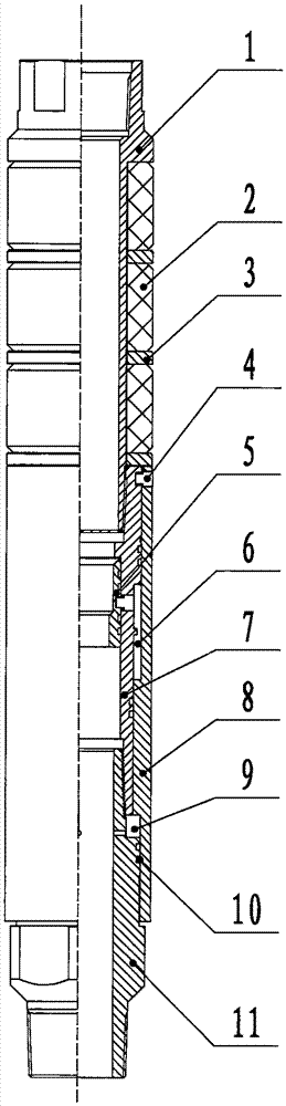
[0012] figure 1 Among them, the outer wall of the upper joint 1 is provided with three sets of rubber tubes 2 and spacer rings 3, and the lower part is connected with the central tube 7 of the slider. , the ball seat sliding sleeve 5 is fixedly connected with the slider central tube 7 through the pin 4, and two groups of sealing rings 10 are respectively arranged in the upper and lower sides of the ball seat sliding sleeve groove of the pin 4, and a power slider is provided outside the slider central tube 7. Sleeve 8, the upper end of the power sliding sleeve 8 is in contact with the spacer ring 3, and the lower end is placed on the boss of the lower joint 11. The power sliding sleeve 8 and the slider center tube 7 are fixedly connected by the pin 4, and the slider center tube 7 is provided with The lower joint 11, the lower joint 11 is provided with a water seepage slot, the hydraulic chamber 9 is surrounded by the lower joint 11, the slider center tube 7 and the power slidin...


PUM


Abstract

The invention discloses a hydrostatic pressure sealing type crack packer that comprises an upper joint, a glue cylinder, a separating ring, a pin, a tee sliding sleeve, an air chamber, a slide block center pipe, a power sliding sleeve, a hydraulic chamber, a sealing ring and a lower clutch. The packer can be used more simply; when the pin is broken by pressing and sealing is realized, the packer can be used to maintain the sealing state without supercharging by a ground apparatus; the sealing or even hydrostatic pressure sealing is realized by differential pressure between the air chamber and the hydraulic chamber. The differential pressure sealing structure of the packer has no restriction to over-current area of a matching sand jet, and maximum flow that sandblast amount equal to drift diameter of a tubing string can be realized without sand jet throttling to provide differential pressure. In this way, the packer provides a possibility for large sandblast displacement for the sand jet, and the sandblast efficiency can be improved. The packer can be decompressed conveniently; similar to a throwing sand jet throwing a corresponding releasing ball, the pin is cut off; the air chamber isn't sealed; and the glue cylinder loses extruding effect and rebounds to recover.

Description

technical field [0001] The invention relates to petroleum drilling mechanical equipment, in particular to a hydrostatic pressure setting type fracturing packer. Background technique [0002] Since the reform and opening up, the national economy has grown rapidly, "scientific and technological innovation, independent innovation" has become the mainstream of domestic industrial development, and my country's industry is gradually developing in the direction of intensive, energy-saving, emission-reducing, and low-carbon. Petroleum is the "blood" and economic lifeline of my country's modern industrial development, and is an important strategic resource that affects the stability and security of national energy. In oil extraction, after long-term production of the oil well, the organic matter precipitation and sand production of the reservoir fluid will inevitably cause the blockage of the reservoir pores near the bottom of the well, resulting in a decrease in porosity and permeab...

Claims


Application Information

Patent Timeline
Patent Type & Authority Applications(China)
IPC IPC(8): E21B33/128E21B33/126
CPCE21B33/1285E21B33/1208E21B33/126
Inventor 袁海月王书海
Owner 盐城市畅海精密机械有限公司
Why Eureka
Try Eureka