Pipeline internal water seepage plugging device and construction method thereof

A plugging device and pipeline technology, applied in the direction of pipe elements, pipes/pipe joints/pipe fittings, mechanical equipment, etc., can solve the problem of water seepage in the pipe that cannot be blocked, and achieve the effect of saving costs and speeding up the construction period.

Active Publication Date: 2017-08-29
CHINA NUCLEAR IND 22ND CONSTR
View PDF6 Cites 8 Cited by
  • Summary
  • Abstract
  • Description
  • Claims
  • Application Information

AI Technical Summary

Problems solved by technology

[0008] The invention provides a pipe seepage sealing device and a construction method thereof, which can be used for grouting in pipes of any diameter, thereby solving the problem that water seepage in the pipe cannot be blocked

Method used


Image

  • Pipeline internal water seepage plugging device and construction method thereof
  • Pipeline internal water seepage plugging device and construction method thereof
  • Pipeline internal water seepage plugging device and construction method thereof

Examples


Embodiment 1

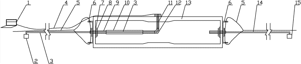
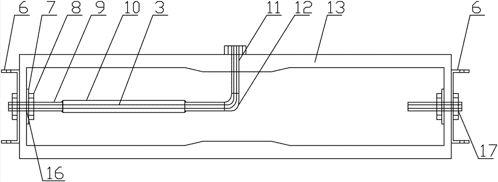
[0043] Such as Figure 1-2 , a pipe seepage plugging device, it includes an air bag 13, the air bag 13 is provided with an air inlet 17, an inlet 16 and an outlet 11.

[0044] Further, the air inlet 17 is connected to the inflation device; the feed port 16 is connected to the pressure tank slurry device; the discharge port 11 is connected to the feed port through a grouting pipeline; the discharge port 16 is set On the side wall of the airbag 13. The air inlet can fill the air bag with air, and the air bag is required to maintain a certain air pressure range, so a barometer is installed at the air inlet to replenish air in time when the air pressure does not meet the requirements.

[0045] Further, traction devices are provided at both ends of the airbag 13 .

[0046] Further, the airbag 13 is made of a high-temperature-resistant rubber tube material, and the wall thickness of the airbag 13 is inconsistent, and the wall thickness at the discharge port 11 is greater than that...

Embodiment 2

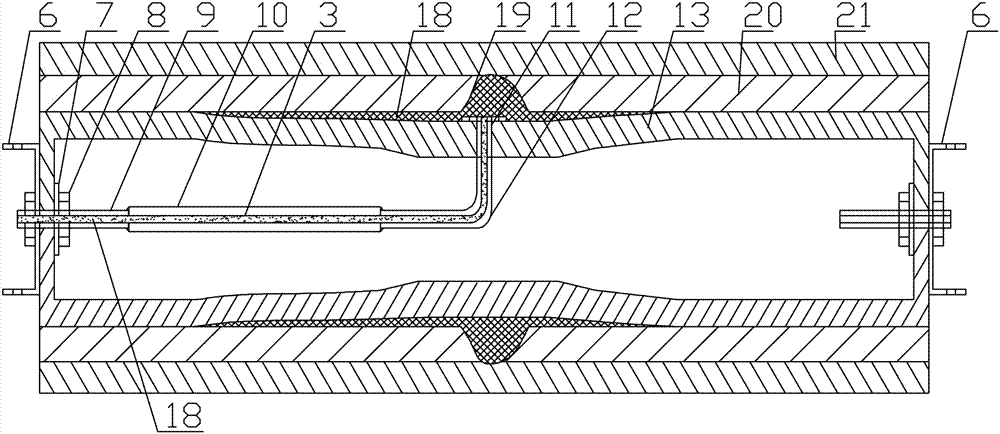
[0058] Such as image 3 , the construction method of water seepage sealing device in pipeline, it comprises the following steps:

[0059] Step1: use the endoscope 4 to go deep into the pipeline 20 to be blocked, and initially determine the position of the leakage point 19 through the image display device 1;

[0060] Step2: Extend the uninflated airbag 13 into the pipeline 20 to be blocked, and adjust its position inside the pipeline 20 to be blocked by pulling the steel wire rope 5 at both ends, so that the discharge port 11 is located at the position of the leakage point 19 Location;

[0061] Step3: Inflate the inside of the airbag 13 through the pressure gauge and the inflation device 15, so that the outer walls of both ends of the airbag 13 and the inner wall of the pipeline 20 to be blocked are bonded and sealed, and an airtight cavity is formed in the middle;

[0062] Step4: Use the pressure grouting machine 2 to inject the plugging material to the leakage point 19 thro...


PUM


Abstract

The invention discloses a pipeline internal water seepage plugging device and a construction method of the pipeline internal water seepage plugging device. The pipeline internal water seepage plugging device comprises an air bag. The air bag is provided with an air inlet, a feeding opening and a discharging opening. The air inlet is connected with an inflation device. The feeding opening is connected with a pressure grouting device. The discharging opening is connected with the feeding opening through a grouting pipeline. The discharging opening is arranged on the side wall of the air bag. The two ends of the air bag are provided with traction devices. The air bag is made of high-temperature-resistant rubber pipe materials. The thicknesses of the air bag are not identical. The wall thickness at the discharging opening is larger than that at other positions. The two ends of the air bag are fixedly provided with gaskets through nuts. The outer walls of the two ends of the inflated air bag can be attached to a pipeline to be repaired in a sealed manner so that a sealed cavity can be formed in the middle of the air bag. By the adoption of the pipeline internal water seepage plugging device, grouting can be conducted inside the pipeline of any diameter, and therefore the problem that water seepage inside the pipeline cannot be plugged is solved.

Description

technical field [0001] The invention relates to the field of pipeline construction devices, in particular to a pipeline seepage sealing device and a construction method thereof. Background technique [0002] During the construction process, cracks will inevitably appear in the concrete, especially at the construction joint position, where tiny cracks always exist, and water seepage occurs at the cracks. The existing seepage sealing methods mainly include the following methods: [0003] Method 1: Bulebao direct plugging method; for environments with large crack width and sufficient operating space, use Dulebao sold on the market to seal the cracks, so as to achieve the purpose of water stop, but for cracks that are small and difficult to Method 2 is often used for the parts of the operation. [0004] Method 2: Pressure grouting method; For areas with small crack widths and difficult operation, pressure grouting is generally used. According to different environments, rigid ma...

Claims


Application Information

Patent Timeline
Patent Type & Authority Applications(China)
IPC IPC(8): F16L55/1645
CPCF16L55/16455
Inventor 张大千刘优生陈慈新刘友平吕丽坤于川
Owner CHINA NUCLEAR IND 22ND CONSTR
Why Eureka
Try Eureka