Integrated type microchannel heat exchanger

A micro-channel heat exchanger, heat exchanger technology, applied in the direction of heat exchanger shell, heat exchange equipment, lighting and heating equipment, etc., can solve problems such as increased flow resistance, medium leakage, system failure, etc.

Pending Publication Date: 2017-08-29
杭州微控节能科技有限公司 +1
View PDF3 Cites 0 Cited by
  • Summary
  • Abstract
  • Description
  • Claims
  • Application Information

AI Technical Summary

Problems solved by technology

The existing micro-channel flow channel reaches the micron level, and the flow channel blockage is easily caused by the pollution of the medium or the impurities in the system, resulting in an increase in the flow resistance of the micro-channel heat exchanger; when the temperature of the medium drops beyond the ...

Method used


Image

  • Integrated type microchannel heat exchanger
  • Integrated type microchannel heat exchanger
  • Integrated type microchannel heat exchanger

Examples


Embodiment 1

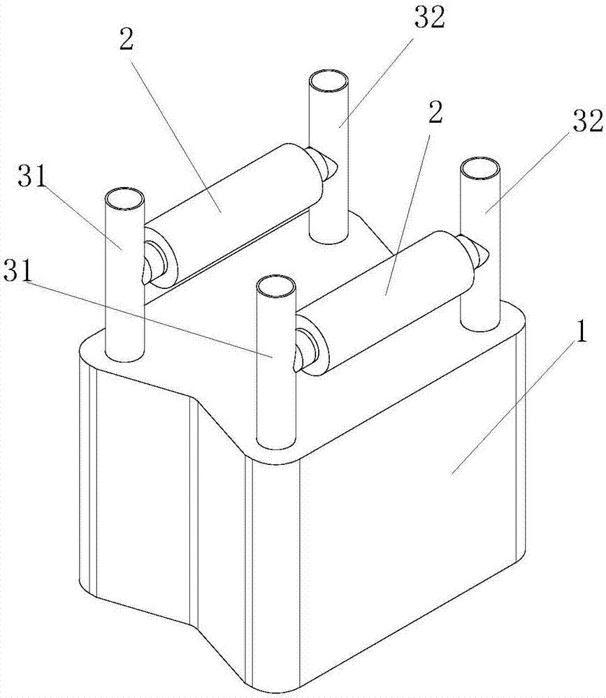
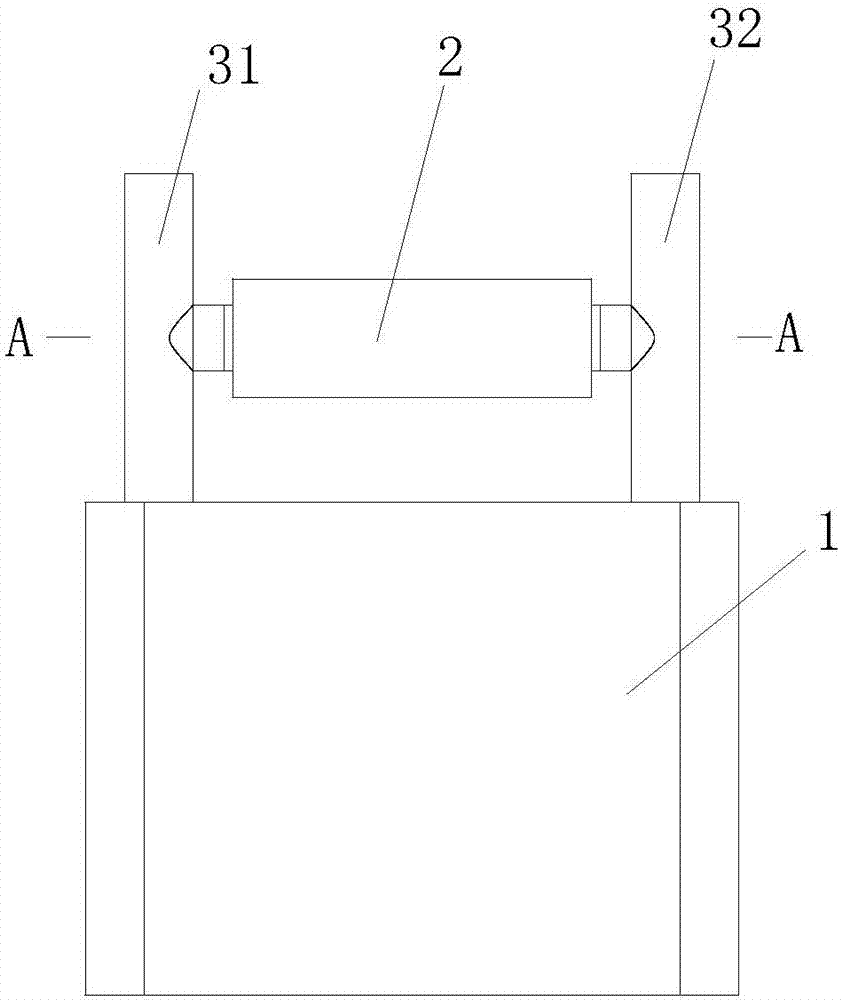
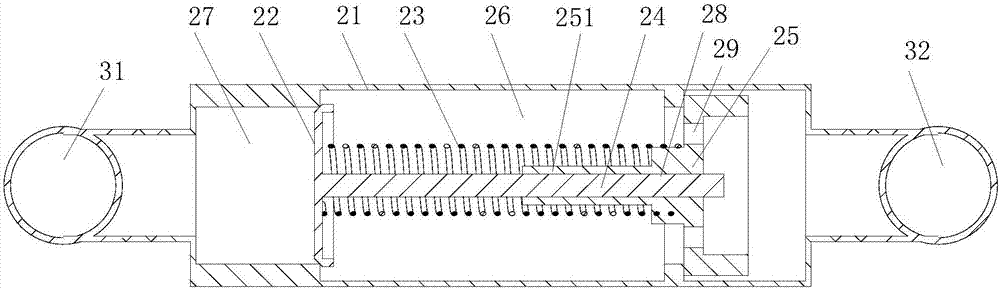
[0015] Example 1: Reference Figure 1-3 . An integrated micro-channel heat exchanger, comprising a heat exchanger core 1, a current collecting circuit, and a pressure sensing device 2. The heat exchanger core 1 is connected with at least a group of current collecting circuits, and the current collecting circuit includes a first The header 31 and the second header 32; the first header 31 and the second header 32 are connected with a pressure sensing device 2 in communication, and the pressure sensing device 2 includes a valve body 21, a plug 22, The spring 23, the support rod 24, the valve seat 25, the valve body 21 is provided with a cavity 26, the left side of the cavity 26 is provided with a valve port 27, the right side is connected with a valve seat 25, and the valve port 27 is provided in the cavity 26 There is a plug 22, the center of the valve seat 25 is provided with a guide hole 28, the support rod 24 penetrates the guide hole 28, and its left end is connected with th...

Embodiment 2

[0017] Example 2: Reference body 1-3. On the basis of Example 1. The heat exchanger core 1 is provided with two or more current collecting circuits, and the first collecting pipe 31 and the second collecting pipe 32 of each collecting circuit are connected with a pressure sensing device 2 in communication.

Embodiment 3

[0018] Example 3: Reference figure 1 , image 3 , Figure 4 . On the basis of Embodiment 1, a temperature sensing package 30 is provided on one end of the valve seat 25 near the spring 23, and the temperature sensing package 30 is wrapped around the outside of the spring 23 on the corresponding side. The temperature sensing package 30 is encapsulated with a temperature sensing medium. The temperature sensing medium melts and expands at high temperature, solidifies and contracts at low temperature, and then squeezes the spring, thereby controlling the elastic force of the spring and the expansion and contraction force of the medium inside the temperature sensing package The degree to which the plug is opened or closed.


PUM


Abstract

The intention relates to an integrated type microchannel heat exchanger which comprises a heat exchanger core, an afflux loop and a pressure sensing device. At least one afflux loop is connected to the heat exchanger core in a communicated manner and comprises a first afflux pipe and a second afflux pipe; the pressure sensing device is connected between the first afflux pipe and the second afflux pipe in a communicated manner, and comprises a valve body, a plug, a spring, a supporting rod and a valve seat, a containing cavity is formed in the valve body, a valve opening is formed in the left side of the containing cavity, the valve seat is connected to the right side of the containing cavity, the plug is arranged at the position, where a valve opening is located, in the containing cavity, a guide hole is formed in the center of the valve seat, the supporting rod penetrates the guide hole, the left end of the supporting rod is connected with the plug, and the spring is arranged between the plug and the valve seat in a sleeving manner; and a circulation hole is formed in the peripheral side of the guide hole of the valve seat, and the two ends of the valve body are through and are connected with the first afflux pipe and the second afflux pipe in a communicated manner. According to the integrated type microchannel heat exchanger, the reliability of the microchannel heat exchanger is improved, and the service life of the microchannel heat exchanger is prolonged.

Description

Technical field [0001] The invention relates to a microchannel heat exchanger, in particular to an integrated microchannel heat exchanger. Background technique [0002] The micro-channel heat exchanger is a three-dimensional structure manufactured by special processing methods that can be used for heat exchange between media. The internal flow channel size of the micro-channel heat exchanger reaches the micron level, which is a micro-scale heat transfer structure, which can greatly increase the flow rate of the medium in the flow channel and improve the heat exchange efficiency, but at the same time it will also increase the flow resistance of the medium. The existing microchannel flow channel reaches the micron level, and the flow channel is easily blocked due to the pollution of the medium or the impurities in the system, which causes the flow resistance of the microchannel heat exchanger to increase; when the temperature of the medium drops beyond the use temperature range, th...

Claims


Application Information

Patent Timeline
IPC IPC(8): F28F9/02F28F27/02
CPCF28F9/02F28F27/02F28F2220/00
Inventor 马欢李涛林云峰
Owner 杭州微控节能科技有限公司
Why Eureka
Try Eureka