Stent for percutaneous vertebroplasty

A technique of puncture vertebra and plastic surgery, applied in prosthesis, internal bone synthesis, medical science, etc., can solve problems such as extra vertebral fractures, and achieve the effect of risk reduction

Inactive Publication Date: 2017-08-29
优化实验诊断仪有限公司
View PDF7 Cites 0 Cited by
  • Summary
  • Abstract
  • Description
  • Claims
  • Application Information

AI Technical Summary

Problems solved by technology

[0003] The problem with existing stents is that in some cases, the vertebral body can ex

Method used


Image

  • Stent for percutaneous vertebroplasty
  • Stent for percutaneous vertebroplasty
  • Stent for percutaneous vertebroplasty

Examples


Embodiment Construction

[0040] In all embodiments, identical, similar or mutually corresponding elements are denoted by the same reference numerals.

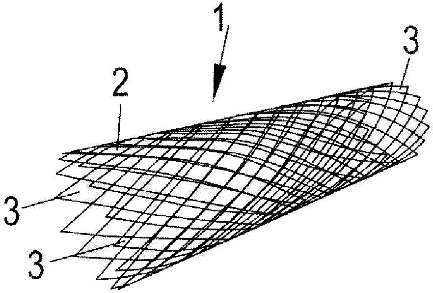
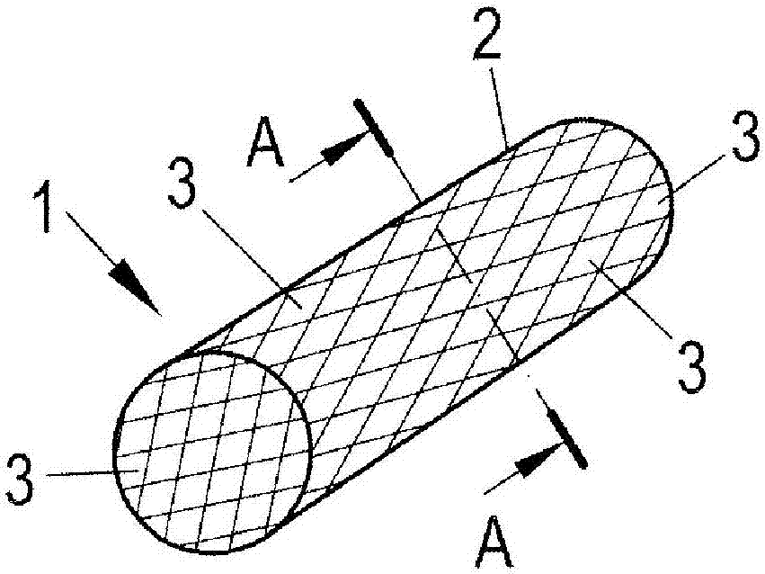
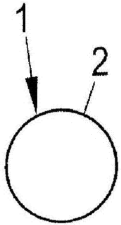
[0041] figure 1 A stent 1 is shown having a tubular body 2 with a reticular structure repeated in both the longitudinal direction and the peripheral direction of the stent 1 such that a plurality of openings 3 are formed in the wall of the body 2 . figure 2 The same stent 1 is shown in a simplified perspective view, from which it can be seen particularly clearly that the stent 1 has a circular cross section. In this respect, the circular cross-section of the support 1 is the same over the entire length of the support 1 , so that the body 2 forms a cylindrical casing with the opening 3 . In this respect, the opening 3 has a rhomboid shape, and since the stent 1 is transformed from a compressed state (not shown) with a clearly reduced diameter to figure 1 with figure 2 The expanded state shown in , in which the opening 3 is enlarged to enable the ex...


PUM


Abstract

The invention relates to a stent for percutaneous vertebroplasty having a substantially tubular body, which can be transferred from a compressed state to an expanded state. Both, in the longitudinal direction and in the peripheral direction of the stent, the wall of the tubular body has a plurality of openings, which ensure the expansion. At least in the expanded state, the stent has a cross-sectional shape that deviates from a circular shape.

Description

technical field [0001] The present invention relates to a stent for percutaneous vertebroplasty, the stent having a generally tubular body that can be transformed from a compressed state to an expanded state, wherein the wall of the tubular body has a plurality of openings, the plurality of The two openings ensure the expansion of the stent in both the longitudinal direction and the peripheral direction. Background technique [0002] This scaffold is used in percutaneous vertebroplasty to treat vertebral fractures. In this procedure, the stent is minimally invasively introduced percutaneously into the vertebral body by an application cannula, with the stent in a compressed state. Once the stent has been positioned within the collapsed vertebral body (which is usually done under x-ray observation), the stent is transitioned from the compressed state to the expanded state. This is currently typically accomplished by corresponding balloon inflation. In this aspect, the stent...

Claims


Application Information

Patent Timeline
IPC IPC(8): A61F2/44A61B17/88A61B17/70
CPCA61B17/7097A61B17/8858A61F2/44A61F2/2846A61F2002/30092A61F2002/30115A61F2002/30125A61F2002/30153A61F2002/30154A61F2002/30205A61F2002/30273A61F2002/30327
Inventor 哈拉尔德·菲舍尔
Owner 优化实验诊断仪有限公司
Why Eureka
Try Eureka