Rotor spinning machine comprising a plurality of working positions and a suction device

A textile machine and airflow technology, which is applied in the field of airflow textile machines with multiple stations and air extraction devices, can solve the problems of difficult machine maintenance and cleaning, difficult access, etc., and achieve a low-cost operation mode, save energy, and reduce pressure. effect of loss

Active Publication Date: 2017-08-29
RIETER INGOLSTADT GMBH
View PDF13 Cites 7 Cited by
  • Summary
  • Abstract
  • Description
  • Claims
  • Application Information

AI Technical Summary

Problems solved by technology

But with this structure, it is difficult to access the parts placed in the middle shelf, and the maintenance and cleaning of the machine become difficult

Method used


Image

  • Rotor spinning machine comprising a plurality of working positions and a suction device
  • Rotor spinning machine comprising a plurality of working positions and a suction device
  • Rotor spinning machine comprising a plurality of working positions and a suction device

Examples


Embodiment Construction

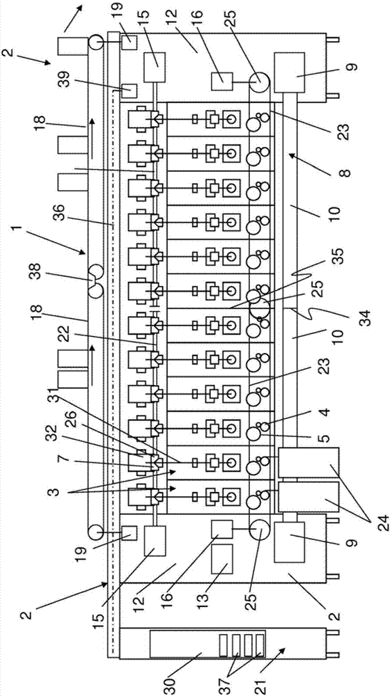
[0034] figure 1 A schematic illustration of an air spinning machine 1 is shown, which is particularly suitable for arranging a plurality of work stations 3 side by side in the longitudinal direction of the air spinning machine 1 . The air spinning machine 1 has a plurality of work stations 3 arranged next to each other between two end parts 2 , each of which has a plurality of working elements 4 , 5 , 6 , 7 in a known manner for producing and winding yarn 31 . Each station 3 has a feed device 4 by means of which the fibrous material is transported from a storage container 24 to a debonding device 5 . The debonding device supplies the fiber material debonded into individual fibers to the spinning rotor 6 , where the fiber material is spun into a yarn 31 and finally wound on a bobbin 32 by means of a winding device 7 .

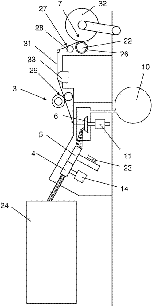
[0035] figure 2 The working elements 4 , 5 , 6 , 7 are precisely shown in the schematic sectional view of the workstation 3 . according to figure 2 , can...


PUM


Abstract

The invention discloses a rotor spinning machine comprising a plurality of working positions and a suction device. The rotor spinning machine has a plurality of working positions (3) arranged next to each other in the longitudinal direction of the rotor spinning machine (1) between two front ends (2) of the rotor spinning machine, each working position having a plurality of working units for producing and winding up a yarn (31). The working units comprise at least one feed device (4), an opening device (5), a spinning rotor (6) and a winding device (7). The rotor spinning machine further comprises a suction device (8) for producing a negative spinning pressure at the working positions. The suction device comprises at least two separate negative pressure sources (9), a negative pressure source being arranged at each of the two front ends of the rotor spinning machine, and each negative pressure source being connected to a separate negative pressure channel (10) which extends only over a part of the working positions in the longitudinal direction of the rotor spinning machine. Every working position has an individual drive (11), in particular an electrical individual drive for the spinning rotor.

Description

technical field [0001] The invention relates to an air spinning machine having a plurality of stations which are arranged side by side on at least one longitudinal side in the longitudinal direction of the air spinning machine between two end-side ends of the air spinning machine During the period, these stations have a plurality of working mechanisms for making and winding yarn respectively, wherein the working mechanism includes at least one feeding device, loosening device, spinning rotor and winding device, and the air spinning machine also There is an air extraction device for generating a low pressure of weaving at the station. Background technique [0002] For air spinning machines it has long been commonplace in the prior art to drive all working mechanisms of the stations from the center in order to be able to drive these machines economically. Here, the individual working elements of the same type are driven by a central drive arranged at the end of the air spinni...

Claims


Application Information

Patent Timeline
Patent Type & Authority Applications(China)
IPC IPC(8): D01H4/08
CPCD01H4/08D01H1/16D01H4/06D01H4/14D01H11/005F16C17/08F16C32/0442
Inventor R·波赫A·斯蒂芬G·沙夫勒M·马奇科
Owner RIETER INGOLSTADT GMBH
Why Eureka
Try Eureka