Vertical take-off and landing aircraft

a vertical take-off and landing aircraft technology, applied in vertical landing/take-off aircraft, power plant types, transportation and packaging, etc., can solve the problems of greatly reduced forward flight characteristics of efficient hover equations, and achieve energy-saving operation, reduce the overall parasitic drag of each lift rotor housing, and minimize aerodynamic drag during flight

Inactive Publication Date: 2019-09-05
VEROPLANE INC
View PDF0 Cites 17 Cited by
  • Summary
  • Abstract
  • Description
  • Claims
  • Application Information

AI Technical Summary

Benefits of technology

[0022]Alternatively the closure arrangement may include a louver system, which may be most appropriate to position on at least one of the outlets of the thrusters, particularly as the louver elements may pivot away from the outlet to the open position and so will be energy efficient to operate.
[0023]Beneficially, the closure arrangement is operable to close off the intake and / or outlet openings, so serve to minimize aerodynamic drag during flight. However, they may also provide protection for the rotors when not operating, by providing a physical cover against foreign object damage.
[0024]In other embodiments, the airflow manipulation device may include an air curtain system arranged about a respective intake of at least one of the thrusters. The air curtain system may comprise openings, ports, or jet passages arranged to inject or delivery pressurized air into the boundary layer travelling over the upper surface of the rotor housing during flight. The air blast will cut off and / or also extend boundary layer laminar flows over and or around said intake openings in order to manipulate the boundary layer air streams in such a way as to decrease the overall parasitic drag of each lift rotor housing. They may also benefit an overall manipulation of the cruise speed related boundary layer air streams.

Problems solved by technology

These disk loadings while producing highly efficient hover equations suffer from greatly reduced forward flight characteristics.

Method used


Image

  • Vertical take-off and landing aircraft
  • Vertical take-off and landing aircraft
  • Vertical take-off and landing aircraft

Examples


Embodiment Construction

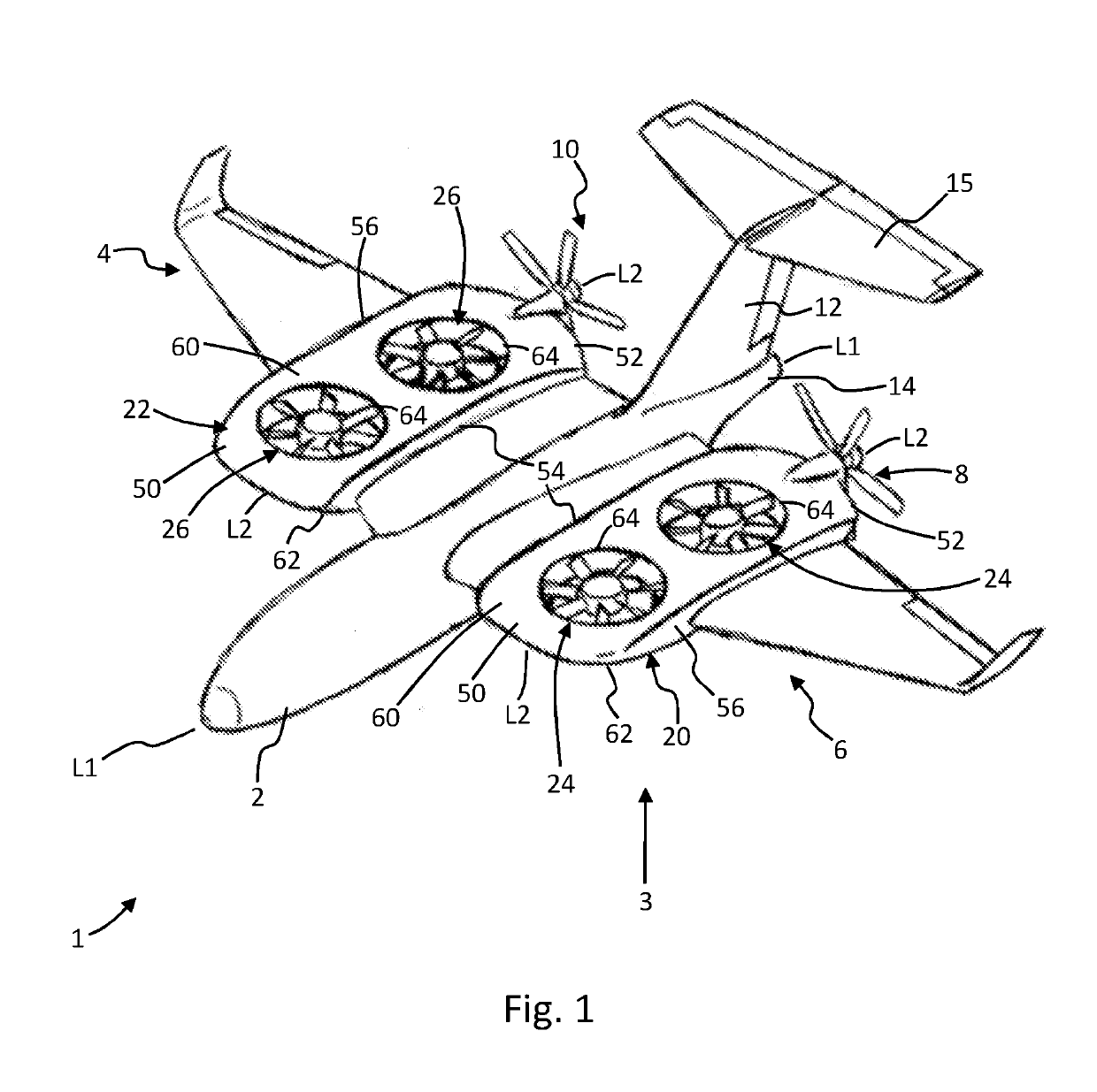
[0046]With reference firstly to FIG. 1, there is shown a VTOL aircraft as an example of the type of aircraft into which the embodiments of the invention may be incorporated. The VTOL Aircraft 1 comprises of a main fuselage 2, disposed centrally, a right main wing section 4 and a left wing section 6. The left main wing section 6 mounts onto and / or is extended from the left side of the main fuselage, and the right wing 4 as well, mounts onto and / or is extended from the right side of the main fuselage 2.

[0047]A horizontal stabilizer 12 extends upwardly from a tail section 14 (or empennage) of the main fuselage 2 and terminates at a laterally extending vertical stabilizer 15 forming what is largely known in the art as a “T-Tail” assembly comprising of both horizontal and vertical stabilizing and control surfaces. It should be noted that this is just an example and other tail configurations are applicable such as twin-booms, mid-mounted vertical stabilizers, V-tail assembly, for example....


PUM


Abstract

A lift rotor or ‘thrust’ system or assembly for a VTOL aircraft, comprising first and second lifting thrusters or rotors contained within a housing, the housing containing a leading edge, a trailing edge, a upper surface and a lower surface; wherein the housing includes one or more airflow manipulation devices provided on or associated with the housing configured to manage the airflow into or through at least one of the first and second rotors. In other aspects, the invention embraces an aircraft wing including a lift thruster system as defined above, and also an aircraft comprising such a lift thruster system.

Description

FIELD OF THE INVENTION[0001]The invention is directed to schemes for vertical take-off and landing aircraft (VTOL) and control techniques for such aircraft. Embodiments of the invention relate to a lift assembly for an aircraft, and to an aircraft incorporating a lift assembly.BACKGROUND TO THE INVENTION[0002]There are many different types of VTOL aircraft designs. One well known method for accomplishing VTOL flight is via tilt-rotor designs (e.g. V22 Osprey) where typically two or more larger propellers or rotors are mounted on pivoting axles at the ends of wingspans on these aircraft, and they then tilt or pivot from vertical orientation for lift off, to horizontal orientations as they transition through and enter normal forward flight mode. One of the major downfalls of this design is the dangerous time while the rotors are slowly tilting toward forward flight orientation. As the rotors tilt, their overall vertical lift force that was supporting the aircraft's weight is quickly r...

Claims


Application Information

Patent Timeline
Patent Type & Authority Applications(United States)
IPC IPC(8): B64C29/00B64C11/00B64C11/46B64C23/06B64C7/02B64C9/02B64C9/22
CPCB64C29/0025B64C11/001B64C11/46B64C23/06B64D35/04B64C9/02B64C9/22B64D27/14B64D35/02B64C7/02B64D27/12Y02T50/40B64C27/20B64C27/22
Inventor MORGAN, BRIAN
Owner VEROPLANE INC
Why Eureka
Try Eureka