Pet detector timing calibration

A technology of detectors and radiation detectors, applied in the field of medical imaging, can solve the problems of reducing the timing accuracy of crystals, etc.

Active Publication Date: 2017-08-29
KONINKLJIJKE PHILIPS NV
View PDF9 Cites 12 Cited by
  • Summary
  • Abstract
  • Description
  • Claims
  • Application Information

AI Technical Summary

Problems solved by technology

Including scattered photons in the measurement also reduces crystal timing accuracy

Method used


Image

  • Pet detector timing calibration
  • Pet detector timing calibration
  • Pet detector timing calibration

Examples


Embodiment Construction

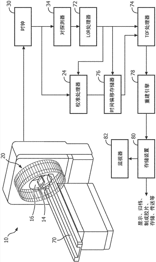
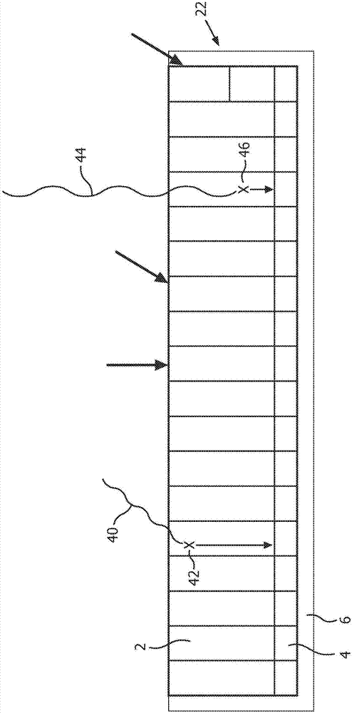
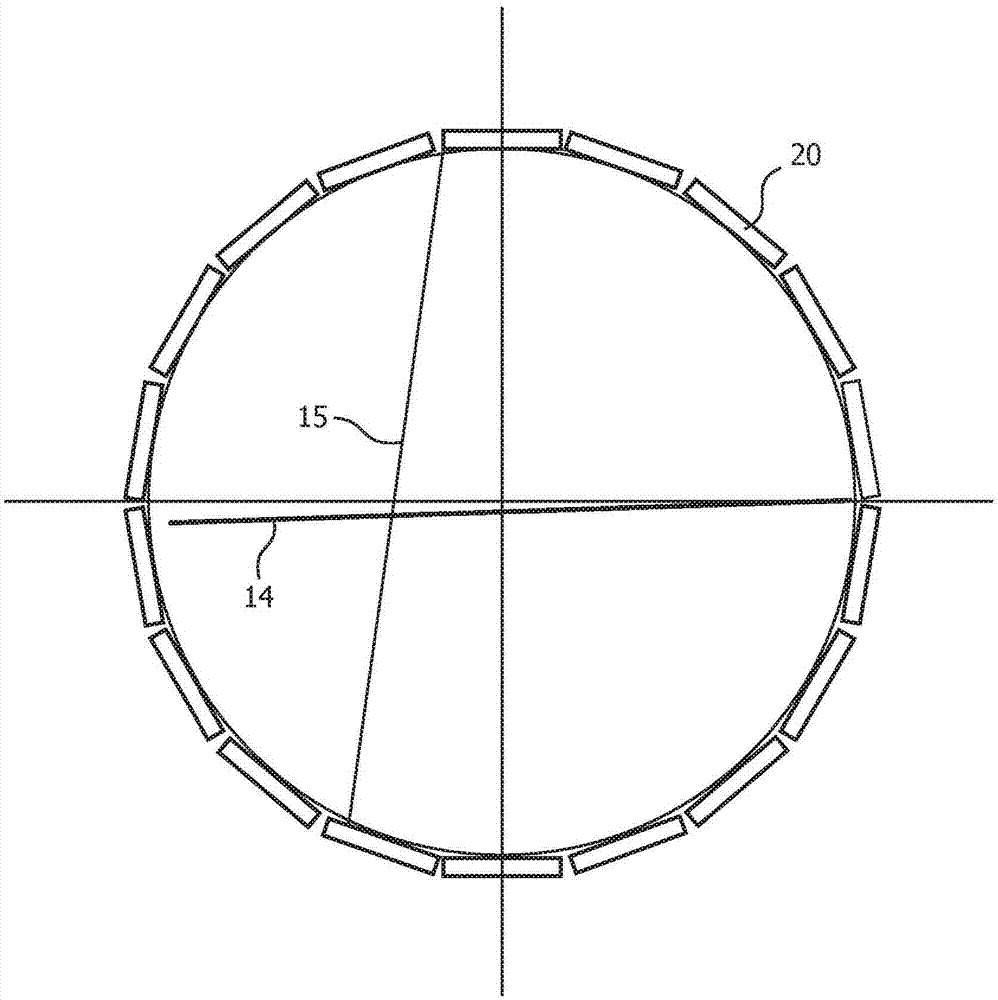
[0018] The present application provides systems and methods for calibrating timing in PET systems. Said disadvantages can be overcome by the present application. This application uses a flake source or a variation of the flake source to calibrate TOF-PET timing. The source is a large flat slice such that all LORs to intersect the object pass through the slice source when placed parallel to the central axis (eg, horizontally in the center). The flake source may be rotated such that all LORs intersect the flake source in at least one orientation. Using a slab source or similar type of source for timing calibration results in large LOR coverage, negligible scatter contribution, and varies narrow activity distributions along each LOR. Also, there is no need to indirectly derive LOR timing for any LOR since there is a direct coincident event count available for each active LOR. Since the activity is narrowly distributed along each LOR (ie, essentially at a single point), the num...


PUM


Abstract

A diagnostic imaging system comprises a plurality of radiation detectors (20) configured to detect radiation events emanating from an imaging region. The system comprises a calibration phantom (14) configured to be disposed in the imaging region spanning substantially an entire field of view and to generate radiation event pairs that define lines-of-response, wherein the calibration phantom is thin such that each LOR intersects the calibration phantom along its length, the thickness of the phantom being smaller than the length of the LORs. A calibration processor (24) receives input of the radiation detectors and calculates an incidence angle independent crystal delay tau i for each detector. The calibration processor (24) constructs a first look-up table for the timing correction of each LOR and a second look-up table for the angle depth of interaction correction for each crystal by combining tau i and eta i.

Description

technical field [0001] This application relates generally to medical imaging. It has particular application in connection with the calibration of positron emission tomography (PET) detectors and will be described with particular reference thereto. However, it should be understood that it is also applicable to other usage scenarios and is not necessarily limited to the aforementioned applications. Background technique [0002] In time-of-flight (TOF)-enabled PET, the reconstruction algorithm relies on precise timing calibration for each line of response (LOR). Current calibration methods use positron emitting point sources, cylinder sources, or patient data to determine scintillator crystal timing. However, these sources are not favorable for timing calibration of PET systems. Point sources are small and direct event counting is not available for many valid LORs. The cylindrical source is so large that along each LOR the source is distributed over a large area. [0003] ...

Claims


Application Information

Patent Timeline
Patent Type & Authority Applications(China)
IPC IPC(8): G01T1/29A61B6/00A61B6/03
CPCA61B6/037A61B6/585G01T1/2985A61B6/4266A61B6/583
Inventor 叶京汉宋犀云T·L·劳伦斯S·X·王
Owner KONINKLJIJKE PHILIPS NV
Why Eureka
Try Eureka