
Integrated rotation driving executor

A rotary drive and actuator technology, applied in the field of robotics, can solve problems such as the circuit is susceptible to external interference, weak overload capacity, and damage to expensive equipment

Active Publication Date: 2017-09-01
CLOUDMINDS SHANGHAI ROBOTICS CO LTD
View PDF7 Cites 16 Cited by
  • Summary
  • Abstract
  • Description
  • Claims
  • Application Information

AI Technical Summary

Problems solved by technology

However, rigid joints cannot respond to the external environment in a timely manner, which makes robots equipped with rigid joints poor compatibility, low energy efficiency and high energy consumption. When a robot collides with the environment rigidly, it may damage expensive equipment or injure humans and animals.
[0004] At present, the servo is generally separated from the driver and the motor, and the two are connected by cables, so there are many connecting lines, the wiring is troublesome, and the lines are susceptible to external interference, poor contact or aging can easily affect the overall operation
In particular, with the increase of the distance of the encoder line and the enhancement of external environment interference, the communication quality will decrease significantly
[0005] Most of the existing servos use inner rotor motors, which have high cost, large volume, small torque and weak overload capacity
The separation of motor, driver, and encoder makes the line cluttered and the anti-interference ability weak, and leads to a large overall size
[0006] The existing servo has a large overall volume, low cost performance, low energy utilization rate, and low security

Method used


Image

  • Integrated rotation driving executor
  • Integrated rotation driving executor
  • Integrated rotation driving executor

Examples


Embodiment Construction

[0034] Specific embodiments of the present invention will be described in detail below in conjunction with the accompanying drawings. It should be understood that the specific embodiments described here are only used to illustrate and explain the present invention, and are not intended to limit the present invention.

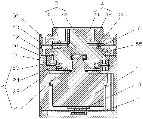
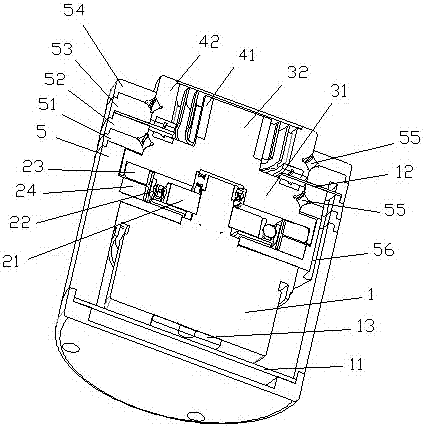
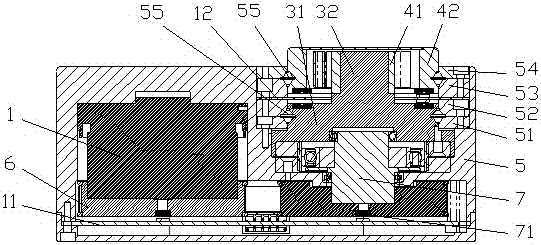
[0035] Please refer to Figure 1 to Figure 3 , figure 1 It is a cross-sectional view of the first specific embodiment of the integrated rotary drive actuator provided by the present invention, figure 2 for figure 1 Another cross-sectional perspective view of the integrated rotary drive actuator shown, image 3 It is a sectional view of the second embodiment of the integrated rotary drive actuator provided by the present invention.

[0036] In a specific embodiment, the present invention provides an integrated rotary drive actuator, including a motor 1, a coaxial reducer 2 and a shaft flange 3; the motor 1 is provided with a motor encoder, and is driven by a...


PUM


Abstract

The invention discloses an integrated rotation driving executor which comprises a motor, a coaxial speed reducer and a shaft flange. The motor is provided with a motor encoder and driven by a driving circuit board. The input end of the coaxial speed reducer cooperates with the motor. The coaxial speed reducer is provided with a speed reducer encoder. The shaft flange is an output shaft provided with a flange plate. The flange plate cooperates with the output end of the coaxial speed reducer. The output shaft outputs a rotation signal. When the driving executor works, the driving circuit board drives the motor, the rotating speed of the motor and the rotating speed of the output end of the coaxial speed reducer can be obtained through the encoders, the rotating speeds can be adjusted through the driving circuit board according to the rotating speed condition, and precise control can be achieved. According to the driving executor, a driver, the motor, the encoders and the coaxial speed reducer are integrated into a small and flexible whole, and mounting and using convenience is improved. The driving executor is compact in structure, small in size, large in output torque, easy to control, high in control precision and high in safety.

Description

technical field [0001] The invention relates to the technical field of robots, in particular to an integrated rotary drive actuator. Background technique [0002] In recent years, with the development of industrial technology, intelligent robots have more contact with people in the fields of industry, medical treatment and service. [0003] Traditional robots use rigid joints with motor-reducer-load linear transmission. Rigid joints have the advantages of simple structure, compact size, and precise positioning, which can meet the requirements of industrial production. However, rigid joints cannot respond to the external environment in a timely manner, which makes robots equipped with rigid joints poor compatibility, low energy efficiency and high energy consumption. When a robot collides with the environment rigidly, it may damage expensive equipment or injure humans and animals. . [0004] At present, the servo is generally separated from the driver and the motor, and th...

Claims


Application Information

Patent Timeline
Patent Type & Authority Applications(China)
IPC IPC(8): B25J19/00
CPCB25J19/0041
Inventor 崔昊天闫巡戈朱威
Owner CLOUDMINDS SHANGHAI ROBOTICS CO LTD
Learn More