Electronic-controlled braking system and controlling method and device thereof

An electronically controlled braking and motor control technology is applied in the field of devices, electronically controlled braking systems, and control methods for electronically controlled braking systems, and can solve problems such as difficulty in braking and inability to continue driving.

Inactive Publication Date: 2017-09-01
上海拿森汽车电子有限公司
View PDF5 Cites 19 Cited by
  • Summary
  • Abstract
  • Description
  • Claims
  • Application Information

AI Technical Summary

Problems solved by technology

However, this method may cause the vehicle to be unable to continue driving after braking, or it may be difficult to brake due to forcibly cutting off the power assist.

Method used


Image

  • Electronic-controlled braking system and controlling method and device thereof
  • Electronic-controlled braking system and controlling method and device thereof
  • Electronic-controlled braking system and controlling method and device thereof

Examples


Embodiment 1

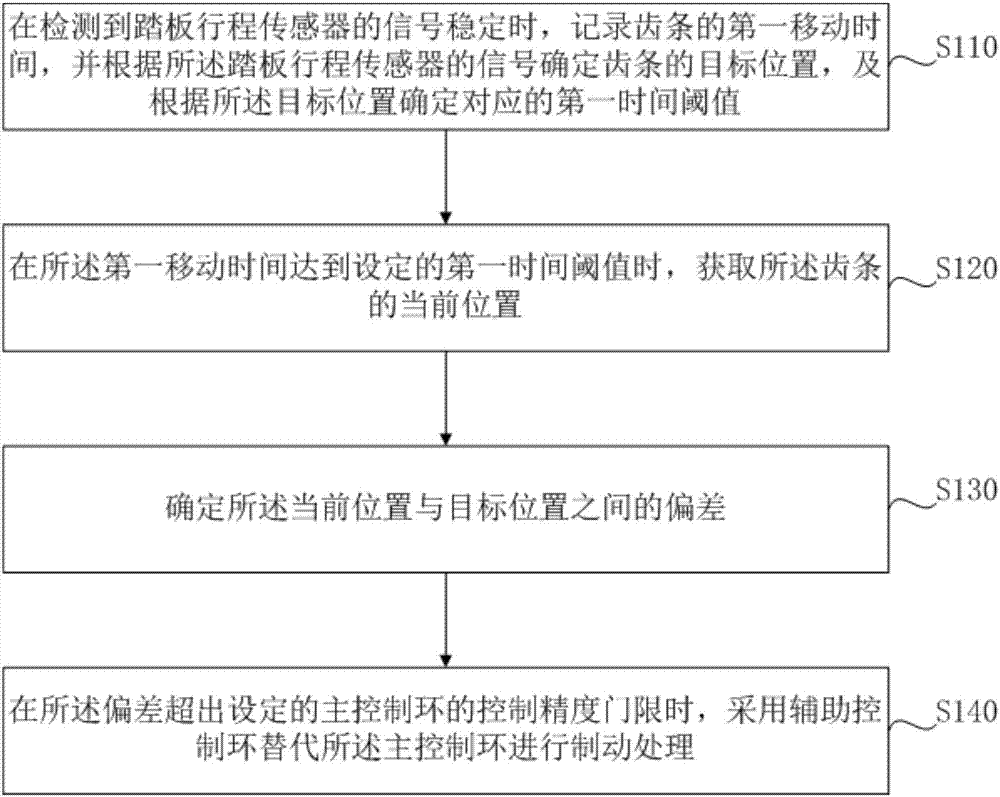
[0033] figure 1 A flowchart of a control method for an electronically controlled braking system provided in Embodiment 1 of the present invention, the method can be executed by a control device of the electronically controlled braking system, and the device can be implemented by hardware and / or software, usually by It is installed in the electronic control unit of the vehicle. The method includes:

[0034] Step 110: When it is detected that the signal of the pedal stroke sensor is stable, record the first movement time of the rack, and determine the target position of the rack according to the signal of the pedal stroke sensor, and determine the corresponding first position according to the target position. time threshold.

[0035] Wherein, the pedal stroke sensor can collect the displacement of the brake pedal under the stepping operation of the driver, and convert the position into an electrical signal and output it to the electronic control unit. The electronic control u...

Embodiment 2

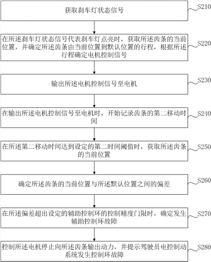
[0050] figure 2 It is a flow chart of the control method of the auxiliary control loop in the control method of the electronically controlled brake system in the second embodiment of the present invention. The method includes:

[0051] Step 210 , acquiring a brake light status signal.

[0052] Wherein, the brake light state signal includes a light-on state signal or a light-off state signal.

[0053] Normally, the brake lights come on when the driver depresses the brake pedal.

[0054] Step 220: When the brake light status signal represents that the brake light is on, obtain the current position of the rack, determine the travel of the rack from the current position to the default position, and determine the motor control signal according to the travel.

[0055] The default position may be the position of the rack corresponding to braking the vehicle. Since the EBS is not controlled for forced braking, the driver can still restart the car after the vehicle is stopped, and...

Embodiment 3

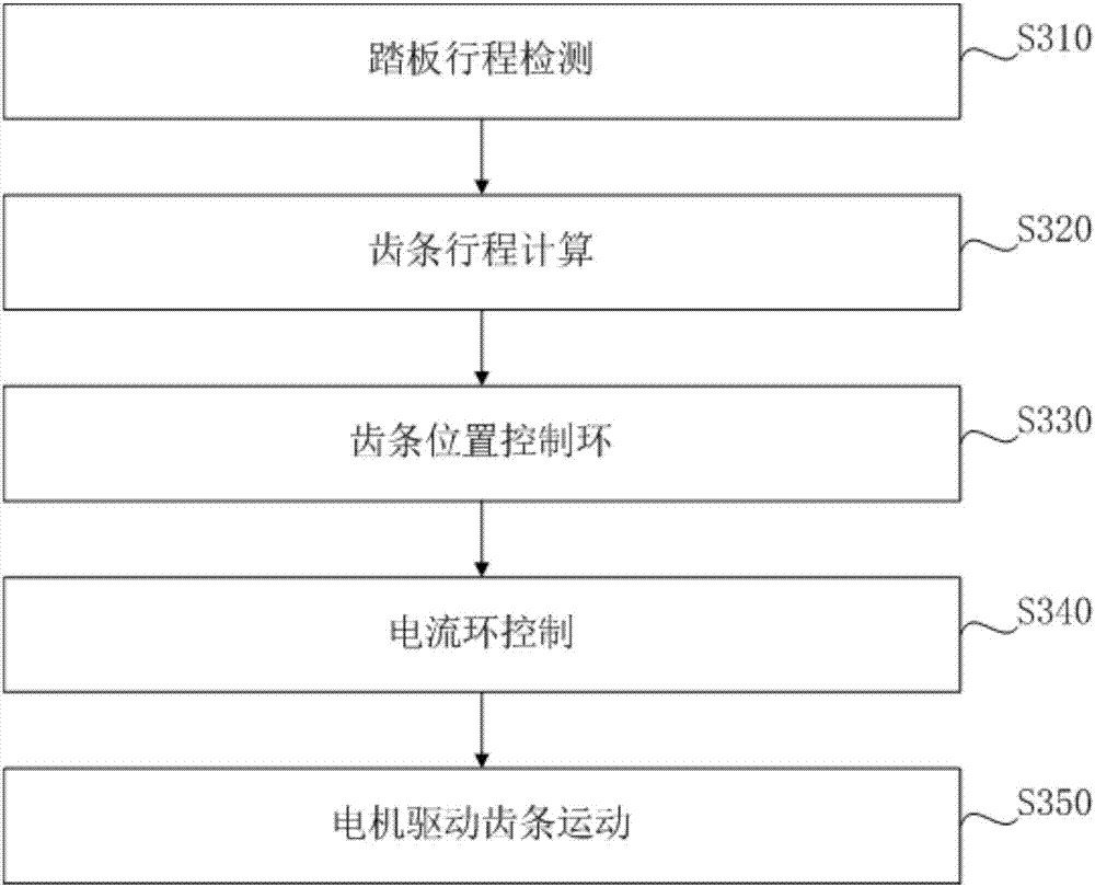
[0071] image 3 It is a flowchart of an EBS control method in Embodiment 3 of the present invention. The method includes:

[0072] Step 310, pedal stroke detection.

[0073] The stroke of the brake pedal is collected by the pedal stroke sensor, and the stroke is proportional to the force with which the user depresses the brake pedal. The pedal travel sensor converts the collected travel information into electrical signals and outputs them to the electronic control unit ECU.

[0074] Step 320, rack stroke calculation.

[0075] The electronic control unit ECU calculates the braking pressure to be output by the electronically controlled braking system according to the received electrical signal corresponding to the stroke information of the brake pedal, so as to calculate the target position that the rack needs to reach. The ECU obtains the current rack position according to the rack position signal collected by the rack position sensor, and calculates the rack stroke that ne...


PUM


Abstract

The embodiment of the invention discloses an electronic-controlled braking system and a control method and device thereof. The control method comprises the following steps that when a signal of a pedal travel sensor is detected to be stable, a first movement time of a gear rack is recorded, a target position of the gear rack is determined according to the signal of the pedal travel sensor, and a first time threshold value is determined according to the target position; when the first movement time reaches the first time threshold value, a current position of the gear rack is obtained; the deviation between the current position and the target position is determined; when the deviation exceeds the given control accuracy threshold of a main control loop, an auxiliary control loop is adopted to replace the main control loop to conduct braking treatment, and the problem that vehicles are unable to restart caused by the electronic-controlled braking system (EBS) being forced to brake or braking difficulty caused by the EBS being forced to cut off power after the traditional EBS algorithm is abnormal is avoided; and manipulative capability of the vehicles is guaranteed through the redundant electronic-controlled algorithm framework, and the risk of traffic accidents of the vehicles is reduced.

Description

technical field [0001] Embodiments of the present invention relate to vehicle control technologies, and in particular, to a control method and device for an electrically controlled braking system and an electrically controlled braking system. Background technique [0002] Braking system Through the evolution of the early mechanical brake system to the late hydraulic brake system, and then to the recent evolution of the electromechanical brake system and the electronic hydraulic brake system, safety and stability have been improved. The basic principle of braking is to make the brake lining and the brake disc or brake drum close to generate friction, and convert the kinetic energy of the vehicle forward or backward into the heat energy generated by friction and dissipate in the atmosphere. [0003] The current electric brake system obtains the information of the force of the driver's stepping on the brake, and the control unit converts the force information of the brake into ...

Claims


Application Information

Patent Timeline
Patent Type & Authority Applications(China)
IPC IPC(8): B60T13/74
CPCB60T13/745
Inventor 姚斌
Owner 上海拿森汽车电子有限公司
Why Eureka
Try Eureka