Glass bead feeding device of glass bead embroidery

A technology of bead embroidery and bead clipping, which is applied in the direction of auxiliary devices, embroidery machines, embroidery machine mechanisms, etc. It can solve the problems of bead embroidery failure, broken thread and needle, and inflexible mechanism movements, etc., and achieves reasonable structure and convenient production Effect

Inactive Publication Date: 2017-09-01
杭州慧群机电设备有限公司
View PDF2 Cites 7 Cited by
  • Summary
  • Abstract
  • Description
  • Claims
  • Application Information

AI Technical Summary

Problems solved by technology

When the needle and thread enter the bead hole, push the bead hard and fall from the clip, which will easily cause thread and needle breakage, thus making bead embroidery fail
In the prior art, magnets are used to realize the damping effect of the bead clamping plate, but because the magnets will magnetize the bead feeding device, the mechanism is prone to dust and the mechanism is inflexible

Method used


Image

  • Glass bead feeding device of glass bead embroidery
  • Glass bead feeding device of glass bead embroidery
  • Glass bead feeding device of glass bead embroidery

Examples


Embodiment 1

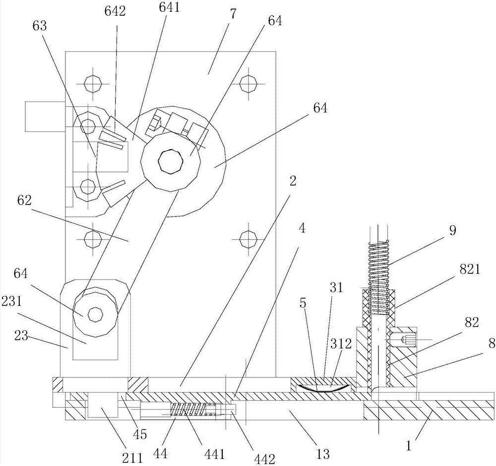
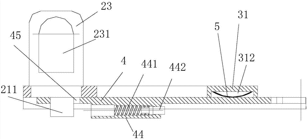
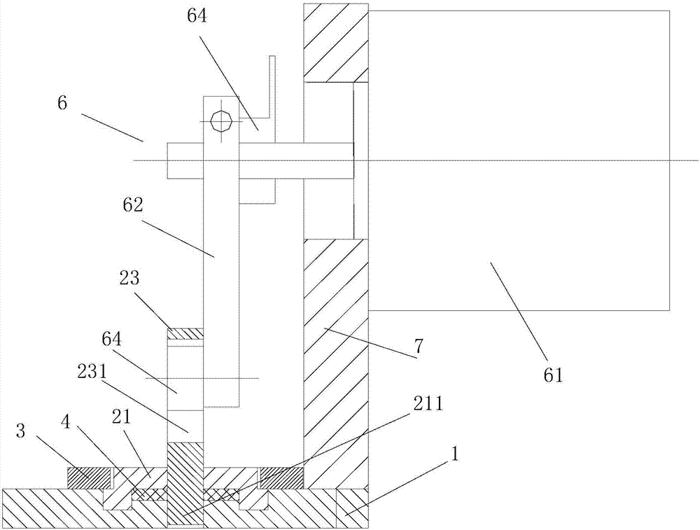
[0030] Embodiment 1: refer to Figure 1-7. A bead embroidery bead feeding device, comprising a fixed base plate 1, a bead clamping sliding plate 2, an elastic bead clamping plate 4, and a lateral sliding drive mechanism 6, the upper side of the fixed base plate 1 is provided with a horizontal chute 11, and the lateral chute 11 Lateral guide grooves 12 are provided on the two sides, and the bead clamping sliding plate 2 includes a push seat 21 and guide plates 22 arranged on both sides of the push seat 21, and the elastic bead clamp plate 4 is clamped and placed on both sides of the guide plate On the lateral chute 11, the guide plates 22 on both sides are guided and connected with the lateral guide grooves 12 on both sides of the lateral chute 11, and the lateral sliding drive mechanism 6 is connected to the push seat 21; the elastic bead clamping plate 4 includes a top plate 42 and the splint 41 that is connected to both sides of the top plate 42 and extends forward. The fro...

Embodiment 2

[0033] Embodiment 2: refer to figure 1 with 8 . A bead outlet seat 8 is provided at the front end of the upper elastic bead clamping plate 4 of the fixed bottom plate 1 . The bead outlet seat 8 is fixedly connected with the fixed bottom plate 1, and the bead outlet seat 8 is provided with a single longitudinal bead outlet hole 81, and a bead outlet conduit 82 is arranged in the longitudinal bead outlet hole, and a connecting portion 821 is provided at the upper end of the bead outlet conduit 82. , and the lower ball spring tube 9 is connected through the connecting portion 821 .

Embodiment 3

[0034] Embodiment 3: refer to figure 1 with 9 . On the basis of Embodiment 1, the bead outlet seat 8 is movably connected to the upper end of the fixed bottom plate 1, and several longitudinal bead outlet holes 81 arranged in a single row or in double rows are arranged on the bead outlet seat 8, and each longitudinal bead outlet hole Bead outlet conduits 82 are respectively provided, and the upper ends of each bead outlet conduits 82 are respectively provided with connecting parts 821 , and the upper ends of each bead outlet conduits 82 are respectively connected with the lower bead spring tubes 9 through the connection parts 821 .


PUM


Abstract

This application relates to a bead feeding device for bead embroidery, which includes a fixed base plate, a bead clamping sliding plate, a pressing plate, an elastic bead clamping plate, and a lateral sliding drive mechanism. The fixed base plate is provided with a horizontal chute on both sides. There is a horizontal guide groove, the bead clip slide plate includes a push seat and guide plates arranged on both sides of the push seat, the elastic bead clip plate is clamped by the two side guide plates and placed on the horizontal chute, the two side guide plates and the two sides of the horizontal chute The horizontal guide groove guides the connection, and the lateral sliding drive mechanism is connected with the push seat; the elastic clamping bead plate includes a top plate and a splint connected to both sides of the top plate and extending forward. The front end of the splints on both sides is close to the front end of the top plate. There are bead clamping bevels opposite to the bevels on both sides. gap, and the two side splints in the corresponding two side guide plates are respectively provided with clamping slopes on the outer sides of their front ends.

Description

technical field [0001] The invention relates to a bead embroidery device, in particular to a bead feeding device for bead embroidery. Background technique [0002] In the decoration production process of the existing fashion clothes and household items, there will be a large number of embroidered bead weaving patterns, which can achieve a better three-dimensional decoration effect. More high-end glass beads are mostly embroidered on the fabric by hand. Embroidery beads have always been a problem in the embroidery machine industry, usually because the whole body of the embroidery beads is relatively uniform, mostly ellipsoid, sphere or cylinder, and the surface contour and pinhole of the beads are difficult to understand during the manufacturing and processing of small beads. Usually uneven, it is difficult to meet the required standards, so it is difficult to accurately locate, and it is difficult to accurately match the pinholes on the embroidery beads with the embroidery n...

Claims


Application Information

Patent Timeline
Patent Type & Authority Applications(China)
IPC IPC(8): D05C7/08D05C13/00
CPCD05C7/08D05C13/00
Inventor 宫国勇胡建华
Owner 杭州慧群机电设备有限公司
Why Eureka
Try Eureka