Eureka AIR delivers breakthrough ideas for toughest innovation challenges, trusted by R&D personnel around the world.

Pumping chamber for shaft seal type nuclear main pump

A nuclear main pump and pressurized water chamber technology, applied in the direction of non-variable pumps, pumps, pump components, etc., can solve the tight installation space, high pressure bearing performance requirements of the pump casing, and the spiral volute can not meet the pressure bearing requirements And other issues

Pending Publication Date: 2017-09-01
HARBIN ELECTRIC POWER EQUIP
View PDF16 Cites 6 Cited by
  • Summary
  • Abstract
  • Description
  • Claims
  • Application Information

AI Technical Summary

Problems solved by technology

Due to the particularity of the working environment of the nuclear main pump, the installation space is tight. The pressure water chamber of the conventional vane pump is composed of the guide vane and the volute. Generally, the vane height is relatively high, and the vane height directly determines the clamping effect of the guide vane on the liquid, eliminating circulation. The axial space of the guide vane and the diffuser tube is relatively large, and the required installation space is also large; the spiral volute adopts a spiral volute, and the flow of the spiral volute at the exit tongue is uneven, and the backflow and pressure pulsation are relatively large. The medium of the nuclear main pump is a high-temperature and high-pressure medium, which requires high pressure bearing performance of the pump casing and long service life. The spiral volute cannot meet the pressure bearing requirements, so the conventional pressurized water chamber is not suitable for the structure of the nuclear main pump.

Method used


Image

  • Pumping chamber for shaft seal type nuclear main pump
  • Pumping chamber for shaft seal type nuclear main pump
  • Pumping chamber for shaft seal type nuclear main pump

Examples


Embodiment Construction

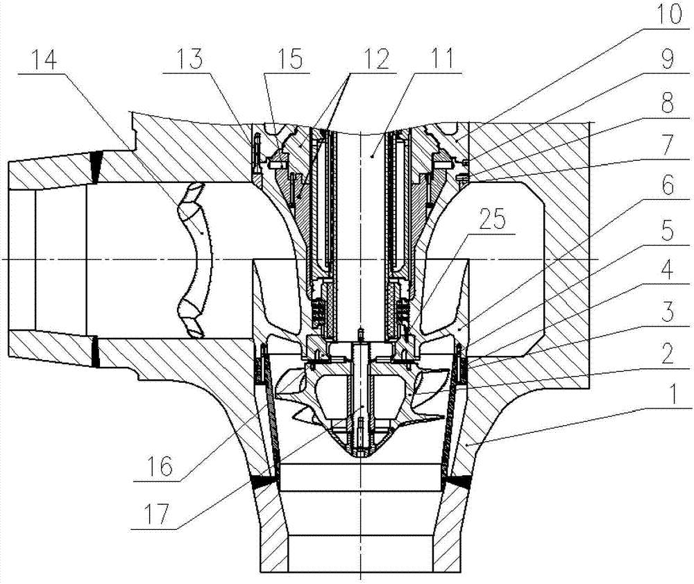
[0013] Such as figure 1 In the pressurized water chamber of a shaft-sealed nuclear main pump shown, the inlet of the vane body 6 is connected to the shroud 3 through a plurality of circumferentially evenly distributed bolts 5, and the shroud 3 is sealed with the pump casing 1 by double seal rings 4. , the inside of the shroud 3 is the impeller 2, the impeller 2 is connected to the pump shaft 11 through the bolt 17; the guide vane body 6 is formed by uniformly distributing a plurality of guide vanes 20 with equal axial flow sections; Uniformly distributed bolts 13 are connected to the sealing chamber 10, and the guide vane body 6 and the sealing chamber 10 realize precise positioning under multiple working conditions through two radial positioning pins 9.

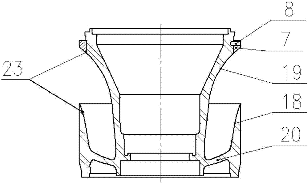
[0014] Such as figure 2 As shown, the guide vane 20 is fixed between the outer edge inner wall 18 and the inner edge outer wall 19, the cone angle at the entrance of the guide vane body 6 is 5.25°, and the cone angle at th...


PUM

PropertyMeasurementUnit
Contraction angleaaaaaaaaaa

Abstract

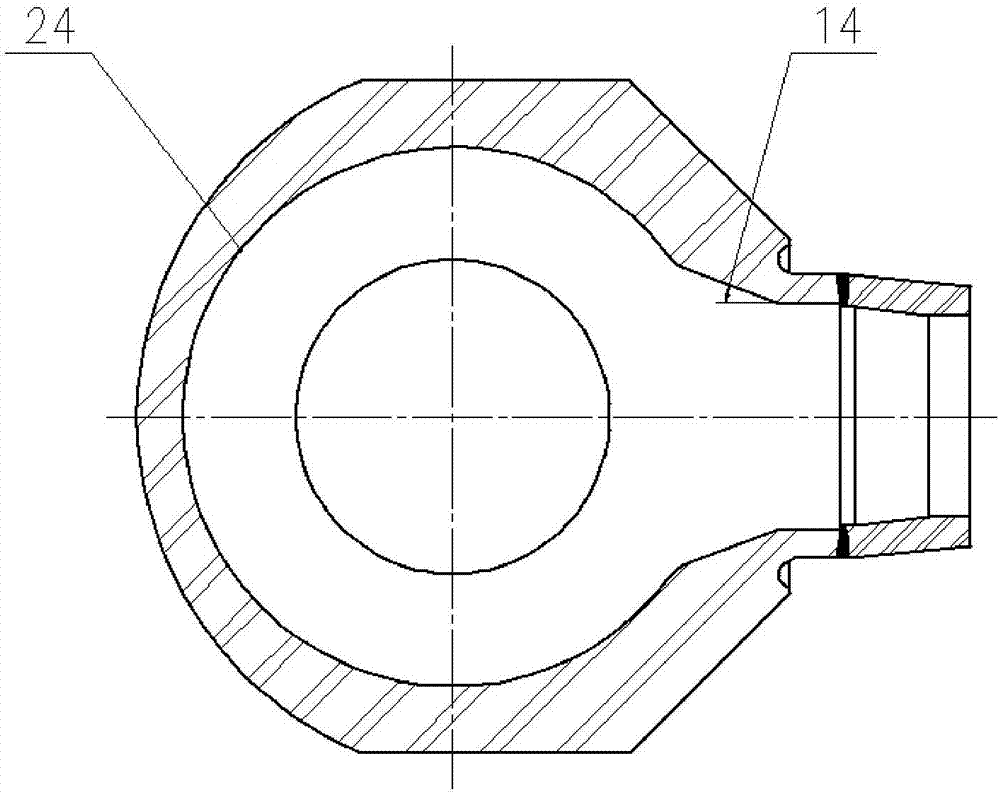
The invention relates to a pumping chamber for a shaft seal type nuclear main pump. The pumping chamber is composed of a guide vane body and a pump case. Due to the limitation of the installation space of the nuclear main pump, for the nuclear main pump guide vane body of the nuclear main pump, the axial installation height is reduced by increasing the number of guide vanes and additionally arranging the structure of double diffusion sections; meanwhile, a thermal insulation device needs to be mounted on a shaft seal pump, and the enough installation space is left for a thermal insulation body in the guide vane body structure; and the corresponding structural treatment is conducted on guide vane inlets and guide vane outlets, the backflow of the inlets is reduced, and the radial circulation of the outlets is eliminated. The pump case is of an annular section direct-output type pumping-out chamber structure, the inner wall is smoothly treated, the angle of throat of an outlet is 20 degrees, the backflow of the outlet of the pumping-out chamber can be reduced, the backflow is the main reason causing the pressure pulse, and the influence of the pressure pulse on the efficiency, the stability, the noise and cavitation of a pump assembly is extremely large. The nuclear main pump water pumping chamber is applied to a 2-nd generation nuclear main pump structure.

Description

technical field [0001] The invention relates to a shaft-sealed nuclear main pump pressure water chamber. Background technique [0002] As a main pump type in the nuclear power industry, the shaft-sealed nuclear main pump has high-efficiency hydraulic performance as the main technical requirement. As an important hydraulic component of the nuclear main pump, the pressurized water chamber directly determines the hydraulic efficiency of the pump unit. Due to the particularity of the working environment of the nuclear main pump, the installation space is tight. The pressure water chamber of the conventional vane pump is composed of the guide vane and the volute. Generally, the vane height is relatively high, and the vane height directly determines the clamping effect of the guide vane on the liquid, eliminating circulation. The axial space of the guide vane and the diffuser tube is relatively large, and the required installation space is also large; the spiral volute adopts a sp...

Claims


Application Information

Patent Timeline
IPC IPC(8): F04D29/42F04D29/44F04D29/66F04D29/58
CPCF04D29/426F04D29/448F04D29/5893F04D29/669F05D2240/12
Inventor 马丹李藏雪江福吕延光张丽平李聪李函霖
Owner HARBIN ELECTRIC POWER EQUIP
Why Eureka
Eureka Blog
Learn More