Design method of pressure measuring rake special for deformed flow channel of wing body fusion airplane ventilation model

A technology of wing body fusion and design method, applied in the field of wind tunnel test, can solve the problems of flow asymmetry, can not meet the requirements of high-speed wind tunnel test, and the difference of total pressure distribution at the outlet is large, and achieves the measurement of total pressure distribution and internal resistance. Accurate calculation, meeting the requirements of high-speed wind tunnel test, and good diversion effect

Active Publication Date: 2020-08-18
INST OF HIGH SPEED AERODYNAMICS OF CHINA AERODYNAMICS RES & DEV CENT
View PDF12 Cites 11 Cited by
  • Summary
  • Abstract
  • Description
  • Claims
  • Application Information

AI Technical Summary

Problems solved by technology

[0005] At present, the design method of pressure measurement rakes in domestic high-speed wind tunnels is established for conventional layout aircraft, resulting in the traditional conventional pressure measurement rakes with simple shape and regular shape, and the number of measurement points is small and symmetrically distributed.
For the new generation of aircraft with wing-body fusion layout design, the internal flow channel is deformed, the cross section is irregular, the flow is asymmetrical, and the total pressure distribution at the outlet is quite different. The traditional pressure rake cannot meet its high-speed wind tunnel test. need
[0006] The shortcomings are mainly reflected in: ①The traditional symmetrical pressure measuring rake has a low matching degree with the irregular flow of the deformed inner flow channel of the wing-body fusion aircraft, and it is difficult to accurately obtain the pressure distribution near the outlet, resulting in relatively large errors in the calculation results of internal resistance. ②In order to improve the measurement accuracy, the pressure measurement points are encrypted on the traditional pressure measurement rake, which will lead to serious blockage and interference of the pressure measurement rake, and the test results cannot truly reflect the flow characteristics of the inner flow channel; ③In the later data processing process, the traditional pressure measurement The calculation weight of each total pressure measurement point on the rake is the same, it is difficult to reflect the contribution of the total pressure difference at different positions to the internal resistance, and the accuracy of the test results is affected

Method used


Image

  • Design method of pressure measuring rake special for deformed flow channel of wing body fusion airplane ventilation model
  • Design method of pressure measuring rake special for deformed flow channel of wing body fusion airplane ventilation model
  • Design method of pressure measuring rake special for deformed flow channel of wing body fusion airplane ventilation model

Examples


Embodiment 1

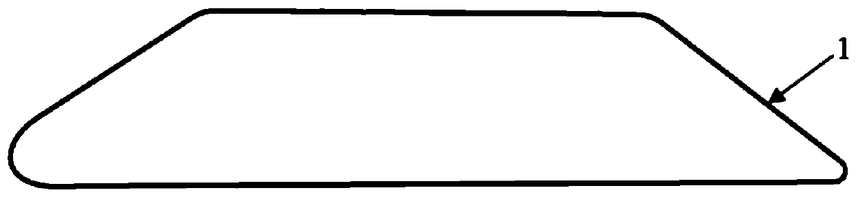
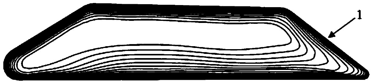
[0047] refer to Figure 1 to Figure 7 As shown, the invention discloses a design method of a special pressure measuring rake for a deformed flow path of a wing-body fusion aircraft ventilation model. The design method of the pressure measurement rake is specifically a design method of providing a special pressure measurement rake for the deformed inner flow path of the aircraft ventilation test model with the wing-body fusion layout.

[0048] The test wind tunnel of this embodiment is a 2.4m×2.4m transonic wind tunnel, and the simulated Mach number is 0.76. The test model is a ventilation model of a wing-body fusion aircraft, and it is required to design a special pressure measuring rake for the deformed inner flow channel of a wing-body fusion aircraft. .

[0049] In a 2.4m×2.4m transonic wind tunnel, the specific operation process of this embodiment includes the following steps:

[0050] a) A section of the deformed inner flow path of the wing-body fusion aircraft is inter...


PUM


Abstract

The invention discloses a design method of a pressure measuring rake special for a deformed flow channel of a wing body fusion airplane ventilation model. According to the invention, the design methodcomprises the steps: acquiring the flow characteristics of the deformed inner flow channel under the interaction of the inner flow of the inner flow channel and the outer flow of the model through anumerical simulation method; performing sub-region division on a measurement cross section according to a numerical simulation result; taking the areas of the sub-regions as weights of calculation ofinternal flow parameters in the sub-regions, determining the number and position distribution of total pressure measuring points and static pressure measuring points on a measuring cross section, anddesigning a rake body to reduce the blocking interference effect. Therefore, the special pressure measuring rake suitable for the deformed internal flow channel of the wing body fusion layout airplaneventilation test model is designed through the process.

Description

technical field [0001] The invention belongs to the technical field of wind tunnel tests, and in particular relates to a design method for a special pressure measuring rake for a deformed flow channel of a wing-body fusion aircraft ventilation model. Background technique [0002] When a fluid such as air or water flows over the surface of an object, there is always a thin layer of uneven velocity distribution near the surface of the object, which is called the boundary layer. In the region inside the boundary layer, the fluid viscosity plays a dominant role; in the region outside the boundary layer, the influence of fluid viscosity is weak. The research results show that the flow characteristics of the inner region of the boundary layer have an important impact on the entire space flow field, and are related to the optimization of the layout schemes of the buried weapon bay and the aircraft inlet and the improvement of equipment performance. Therefore, the flow characteristi...

Claims


Application Information

Patent Timeline
Patent Type & Authority Applications(China)
IPC IPC(8): G01M9/04G01M9/06G01M9/08
CPCG01M9/04G01M9/06G01M9/065G01M9/08
Inventor 许新刘大伟熊贵天陈德华张守友彭鑫赵忠李强武斌刘光远李为群唐新武李阳王伟仲谢易
Owner INST OF HIGH SPEED AERODYNAMICS OF CHINA AERODYNAMICS RES & DEV CENT
Why Eureka
Try Eureka