Interlayer lead-out structure for low-temperature container

A technology of extracting structure and low temperature container, which is applied to the outer wall of container structure, installation device of container structure, non-pressure container, etc. , to ensure the effect of thermal insulation performance

Active Publication Date: 2017-09-01
广东建成机械设备有限公司
View PDF5 Cites 3 Cited by
  • Summary
  • Abstract
  • Description
  • Claims
  • Application Information

AI Technical Summary

Problems solved by technology

[0002] Cryogenic container is a storage tank for transporting and storing low-temperature liquefied gas. It includes an inner tank for loading cryogenic liquid, and an outer shell outside the inner tank. A sandwich is formed between the inner tank and the outer shell, and the interlayer space is filled with Insulating materials and vacuuming are used to ensure that the cryogenic container has good thermal insulation performance. In order to load and unload cryogenic liquids, it is necessary to set up a lead-out structure in the interlayer, but the interlayer lead-out structure in the prior art is generally used A curved pipe connected to the inner tank will be installed in the interlayer space. Since the pipe needs to be bent and takes up a lot of space, a large space needs to be reserved in the interlayer, which will affect the increase in the volume of the inner tank.

Method used


Image

  • Interlayer lead-out structure for low-temperature container
  • Interlayer lead-out structure for low-temperature container
  • Interlayer lead-out structure for low-temperature container

Examples


Embodiment Construction

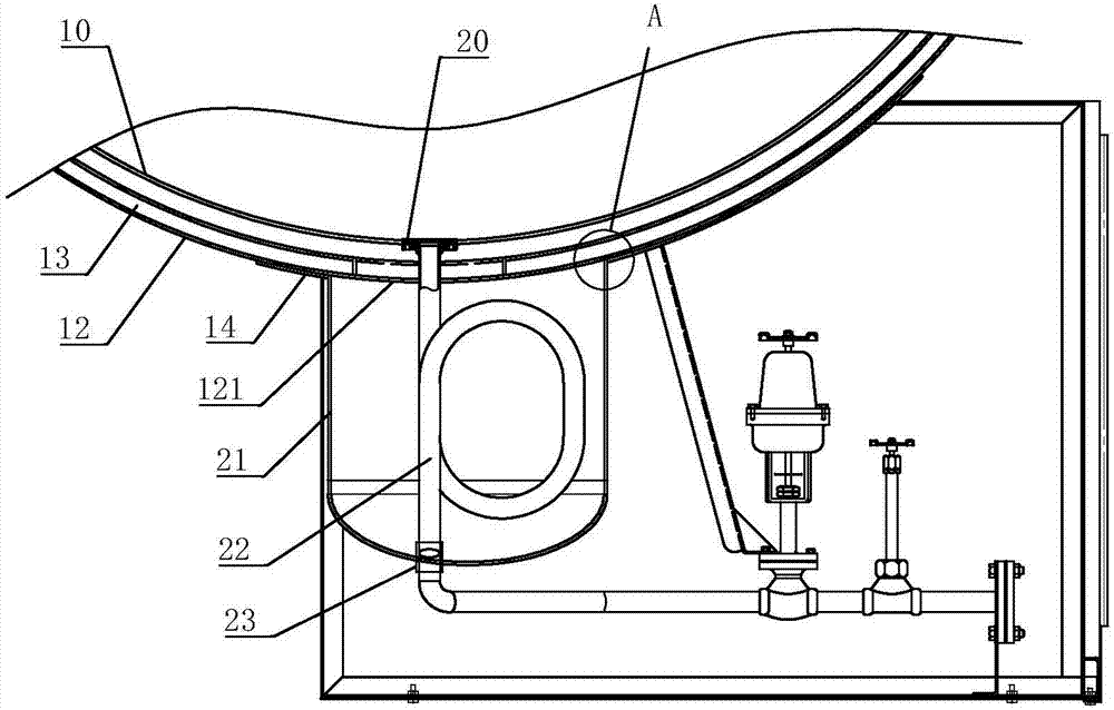
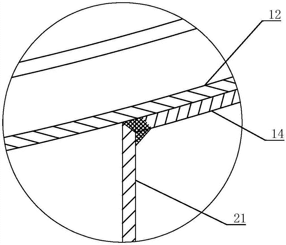
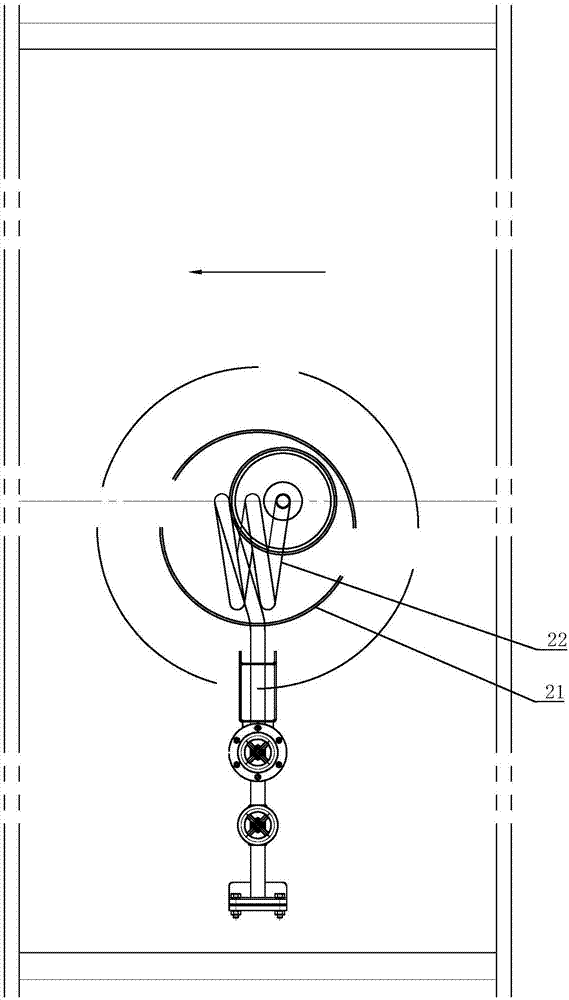
[0032] refer to Figure 1 to Figure 12 , a sandwich lead-out structure for a cryogenic container of the present invention, comprising an inner tank 11, an outer shell 12, a vacuum insulation sleeve 21 and an outlet pipe 22, a vacuum interlayer 13 is formed between the inner tank 11 and the outer shell 12, and the vacuum isolation The sleeve 21 is airtightly connected with the outer shell 12 and communicated with the vacuum interlayer 13. One end of the lead-out pipe 22 is connected to the inner tank 11, and the other end passes through the outer shell 12 to form an overhanging portion, which is set inside the vacuum isolation sleeve 21 There is a curved tube body extending in the direction of cold shrinkage of the liner 11, refer to image 3 with Figure 7 , the direction of the arrow in the figure is the direction of cold shrinkage of the liner 11. Since the present invention arranges the curved pipe body in the vacuum insulation sleeve 21 connected with the vacuum interlay...


PUM


Abstract

The invention discloses an interlayer lead-out structure for a low-temperature container. The interlayer lead-out structure comprises an inner container, a shell, a vacuum isolating sleeve and a lead-out pipe. A vacuum interlayer is formed between the inner container and the shell, and the vacuum isolating sleeve is in sealed connection with the shell and communicates with the vacuum interlayer. One end of the lead-out pipe is connected with the inner container, and the other end of the lead-out pipe penetrates out of the shell to form a stretching part. The stretching part is provided with a bent pipe extending in the inner container cold shrinkage direction in the vacuum isolating sleeve. It is not needed to reserve large space in the vacuum interlayer for mounting of a pipeline, the lead-out pipe can be arranged at the narrow position in the interlayer, and the volume of the inner container is not influenced. In addition, a protruding ring segment and a threaded hole are arranged on a flange, inner container entering is convenient, pressure testing can be conveniently carried out on the inner container before inner container entering, and the performance of the inner container is guaranteed. The pipe is provided with an air seal segment bent upwards, low-temperature liquid can be prevented from flowing to a valve end, the heat transfer rate is reduced, and the insulation performance of the low-temperature container is guaranteed.

Description

technical field [0001] The invention relates to the technical field of cryogenic containers, in particular to an interlayer lead-out structure for a cryogenic container. Background technique [0002] Cryogenic container is a storage tank for transporting and storing low-temperature liquefied gas. It includes an inner tank for loading cryogenic liquid, and an outer shell outside the inner tank. A sandwich is formed between the inner tank and the outer shell, and the interlayer space is filled with Insulating materials and vacuuming are used to ensure that the cryogenic container has good thermal insulation performance. In order to load and unload cryogenic liquids, it is necessary to set up a lead-out structure in the interlayer, but the interlayer lead-out structure in the prior art is generally used A curved pipe connected to the inner tank will be installed in the interlayer space. Since the pipe needs to be bent and takes up a lot of space, a large space needs to be reser...

Claims


Application Information

Patent Timeline
Patent Type & Authority Applications(China)
IPC IPC(8): F17C3/08F17C13/00
CPCF17C3/085F17C13/00F17C2203/0391F17C2205/0302Y02E60/32
Inventor 梁海俊梁健灵梁健东谭锡荣徐健池孔庆勇甄沛权
Owner 广东建成机械设备有限公司
Why Eureka
Try Eureka