Cast welding device for lead-acid storage battery and cast welding method of cast welding device

A lead-acid battery, casting and welding technology is applied to the lead-acid battery manufacturing device and its manufacturing field, which can solve the problems of the influence of the busbar mold, explosion, and increase in manufacturing cost, so as to improve processing efficiency, reduce manufacturing cost, and improve service life. Effect

Inactive Publication Date: 2017-09-05
ZHUZHOU YINGDING AUTOMATION EQUIP TECH
View PDF8 Cites 10 Cited by
  • Summary
  • Abstract
  • Description
  • Claims
  • Application Information

AI Technical Summary

Problems solved by technology

In this method, the temperature of the busbar mold is not uniform, and the temperature of the lead liquid for casting welding is not enough, which will affect the welding effect
[0006] In the casting and welding method of lead-acid battery adopting the first method, the position for casting and welding is generally located above the lead furnace. The temperature at this position is relatively high. After casting and welding, the bus bar mold needs to be cooled. When the busbar mold suddenly encounters cold at a high temperature position, it will affect the busbar mold. In the long run, the service life of the busbar mold will be shortened, resulting in an increase in manufacturing costs; in addition, when the busbar mold is in a high temperature position Sudden cold, over a long period of time, cracks will appear in some welds on the busbar mold, cooling water will flow out from the cracks and fall into the lead furnace, and the liquid lead in the lead furnace is very active. After the water reacts, the hydrogen in the water is replaced, and a large amount of heat is released. The large amount of hydrogen released is ignited at a high temperature, resulting in a higher temperature, and the reaction becomes more and more violent. In the end, it may cause an explosion, and production safety cannot be guaranteed.

Method used


Image

  • Cast welding device for lead-acid storage battery and cast welding method of cast welding device
  • Cast welding device for lead-acid storage battery and cast welding method of cast welding device
  • Cast welding device for lead-acid storage battery and cast welding method of cast welding device

Examples


Embodiment

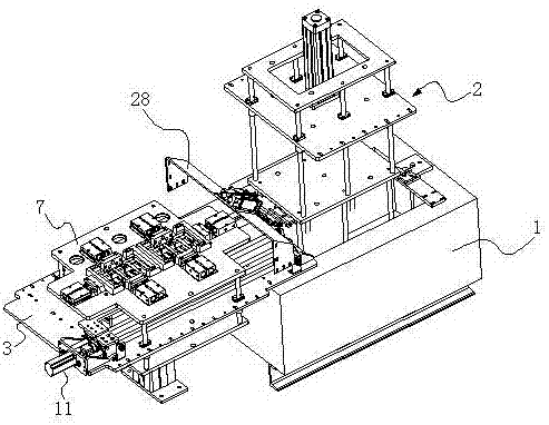
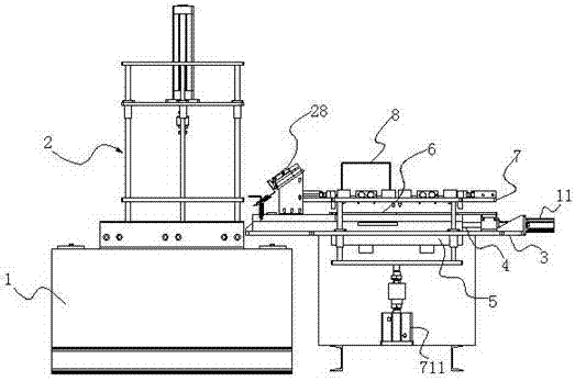
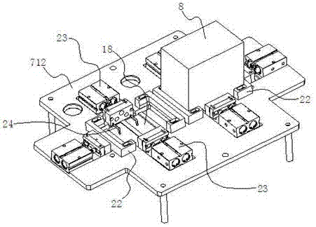
[0038] Example: such as Figure 1 to Figure 5 As shown, a lead-acid battery casting and welding device includes a lifting rail 2 arranged above the lead furnace 1, a workbench 3 arranged on one side of the lead furnace 1, a fixed rail 4 arranged on the workbench 3 and a The water spray mechanism 5 on the workbench 3 and located at the fixed track 4, the bus bar mold 6 is slidably arranged on the fixed track 4 and the lifting track 2 and the bus bar mold 6 can move back and forth between the fixed track 4 and the lifting track 2, On the workbench 3 and above the fixed rail 4, a lifting pallet 7 is provided, and the battery bottom box 8 with multiple pole groups is fixed upside down on the lifting pallet 7; the busbar mold 6 is driven by the lifting rail 2 After immersing in the lead furnace 1 for lead immersion, move the busbar mold 6 to the fixed rail 4, and use the lifting pallet 7 to move down to drive the tabs of multiple pole groups into the lead liquid in the upper cavity...


PUM


Abstract

The invention discloses a cast welding device for a lead-acid storage battery and a cast welding method of the cast welding device. The cast welding device of the lead-acid storage battery comprises a lifting track arranged at the upper part of a lead furnace, a workbench arranged at one side of the lead furnace, a fixed track arranged on the workbench and a water spraying mechanism, wherein the water spraying mechanism is arranged on the workbench and located outside the fixed track; a busbar die is arranged on the fixed track and the lifting track in a sliding manner and can move back and forth between the fixed track and the lifting track; a lifting support plate is arranged on the workbench and at the upper position of the fixed track; a battery bottom box with a plurality of plate groups is inversely fixed on the lifting support plate; and the busbar die is driven to be immersed into the lead furnace for lead immersion through the lifting track, the busbar die is moved to the fixed track, tabs of the plurality of plate groups are driven to be inserted into a lead liquid in a mold cavity of the busbar die for cast welding by using downward movement of the lifting support plate. According to the cast welding device, the service life of the busbar die can be prolonged and the production safety is ensured.

Description

technical field [0001] The invention relates to a lead-acid battery manufacturing device and a manufacturing method thereof, in particular to a lead-acid battery casting welding device and a casting welding method thereof. Background technique [0002] In the past ten years, with the rapid growth of demand for new energy vehicles and renewable energy energy storage, the output and export volume of lead-acid batteries in my country have grown at a rate of about 20% per year, ranking first in starting, energy storage, and power batteries. , the total amount is about 150 million KVA.H / year. Compared with other batteries, lead-acid batteries have the following advantages: 1) The longest time to realize industrial production, the most mature technology, stable performance, reliability, safety, and wide application fields; 2) The lowest production cost, only lithium batteries And about 1 / 3 of the hydrogen-nickel battery; 3), the advantages of recycling and resource reserve are obv...

Claims


Application Information

Patent Timeline
Patent Type & Authority Applications(China)
IPC IPC(8): B22D25/04B22D19/04
CPCB22D19/04B22D25/04
Inventor 郑圣泉黎派龙
Owner ZHUZHOU YINGDING AUTOMATION EQUIP TECH
Why Eureka
Try Eureka