Automatic cross rod clamping and screw locking machine

A screw-locking machine and screw-locking mechanism technology, applied in metal processing, metal processing equipment, manufacturing tools, etc., can solve the problems of large solar panels, inconvenient assembly, low efficiency, etc., and achieve high automation, accurate and efficient assembly Effect

Pending Publication Date: 2017-09-05
KUNSHAN MENGTEZHAN PRECISION ELECTROMECHANICAL CO LTD
View PDF7 Cites 3 Cited by
  • Summary
  • Abstract
  • Description
  • Claims
  • Application Information

AI Technical Summary

Problems solved by technology

[0002] Photovoltaic modules are products that are connected and packaged by multiple photovoltaic cells. The junction box of photovoltaic modules is the key connection device for the solar module system. Solar panels are generally large in size and connected by boards and multiple horizontal and vertical rods. They are all connected by screws. When assembling the product, due to the large size of the entire component, if manual locking screws are used, the efficiency is extremely low. There are also screw locking machines for processing, and the large solar panels need to be transported to the processing table. At the same time, move the cross bar that needs to be locked to the required position, and then use the locking screw device to take the screw to the screw hole for locking. Due to the large size of the solar panel, it is extremely inconvenient to assemble

Method used


Image

  • Automatic cross rod clamping and screw locking machine
  • Automatic cross rod clamping and screw locking machine
  • Automatic cross rod clamping and screw locking machine

Examples


Embodiment Construction

[0023] The following will clearly and completely describe the technical solutions in the embodiments of the present invention with reference to the drawings in the embodiments of the present invention.

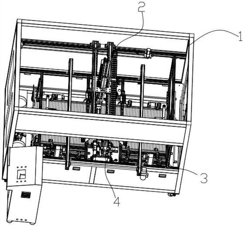
[0024] like figure 1 As shown, the present invention proposes an automatic crossbar locking screw machine, comprising a frame 1, the frame 1 comprising a cuboid frame made of aluminum profiles, and the cuboid frame is also provided with several horizontal frames for easy installation .

[0025] On the frame 1, a crossbar conveying mechanism 2, a plate conveying mechanism 3, a material taking mechanism and at least one locking screw mechanism 4, the plate conveying mechanism 3 is located at the top of the crossbar conveying mechanism 2, and the material taking The mechanism is movably connected to the upper part of the frame 1 and points to the panel conveying mechanism 3. The crossbar conveying mechanism 2 is suitable for conveying the crossbar of the solar panel. This design...


PUM


Abstract

The invention provides an automatic cross rod clamping and screw locking machine. The automatic cross rod clamping and screw locking machine comprises a rack. The rack is provided with a cross rod conveying mechanism, a plate body conveying mechanism, a material taking mechanism and at least one screw locking mechanism. The plate body conveying mechanism is located on the upper portion of the cross rod conveying mechanism. The material taking mechanism is movably connected to the upper portion of the rack and points to the plate body conveying mechanism. According to the automatic cross rod clamping and screw locking machine, matching work can be conducted through the cross rod conveying mechanism and the plate body conveying mechanism; after a plate body where a cross rod needs to be fixed is accurately conveyed through a conveying belt, the cross rod is grabbed through clamping jaws of the material taking mechanism and placed in the corresponding position; the screw locking mechanisms are started, and screws are automatically screwed and locked; manual intervention is not needed in the whole process; the automation degree is high; and assembling is accurate and efficient.

Description

technical field [0001] The invention relates to the field of automation equipment, in particular to a screw machine for automatic cross bar locking. Background technique [0002] Photovoltaic modules are products that are connected and packaged by multiple photovoltaic cells. The junction box of photovoltaic modules is the key connection device for the solar module system. Solar panels are generally large in size and connected by boards and multiple horizontal and vertical rods. They are all connected by screws. When assembling the product, due to the large size of the entire component, if manual locking screws are used, the efficiency is extremely low. There are also screw locking machines for processing, and the large solar panels need to be transported to the processing table. At the same time, move the cross bar to be locked to the required position, and then use the locking screw device to take the screw to the screw hole for locking. Due to the large volume of the sola...

Claims


Application Information

Patent Timeline
Patent Type & Authority Applications(China)
IPC IPC(8): B23P19/06
CPCB23P19/007B23P19/06
Inventor 李剑峰
Owner KUNSHAN MENGTEZHAN PRECISION ELECTROMECHANICAL CO LTD
Why Eureka
Try Eureka