
Wall automatic heat storage and heat removal device and method for achieving wall automatic heat insulation through same

A technology of automatic heat storage and heat removal device, which is applied to heat storage equipment, walls, indirect heat exchangers, etc., can solve the problems of insignificant overall effect and can not solve the problem of heat removal of phase change houses in summer, and achieve excellent natural heat insulation effect, optimal internal and external energy saving, effect of maintaining thermal comfort

Inactive Publication Date: 2017-09-05
HUAZHONG UNIV OF SCI & TECH
View PDF8 Cites 13 Cited by
  • Summary
  • Abstract
  • Description
  • Claims
  • Application Information

AI Technical Summary

Problems solved by technology

The building walls in this scheme objectively have a certain effect of heat preservation and heat insulation, but because it requires the addition of a heat source system, and it is particularly important, in order to reduce energy consumption, it needs to carry out a series of control treatments, such as The opening and closing control, temperature detection and control of various valves require additional energy consumption, making the overall effect not obvious
In addition, this scheme cannot solve the problem of summer heat dissipation of phase-change houses

Method used


Image

  • Wall automatic heat storage and heat removal device and method for achieving wall automatic heat insulation through same

Examples


Embodiment Construction

[0032] In order to make the object, technical solution and advantages of the present invention clearer, the present invention will be further described in detail below in conjunction with the accompanying drawings and embodiments. It should be understood that the specific embodiments described here are only used to explain the present invention, not to limit the present invention. In addition, the technical features involved in the various embodiments of the present invention described below can be combined with each other as long as they do not constitute a conflict with each other.

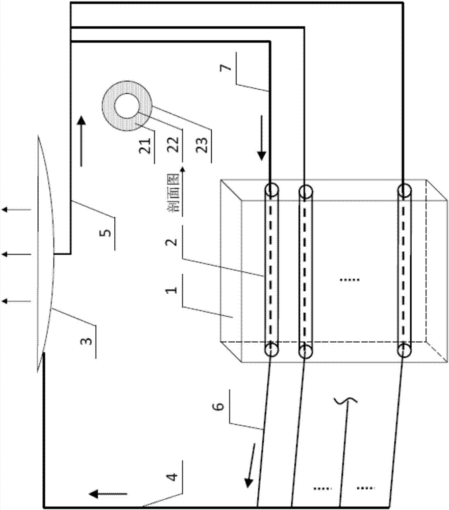
[0033] Such as figure 1 As shown, the intermittent wall automatic heat storage and heat removal device provided according to a preferred embodiment of the present invention includes nested pipes 2 in the wall 1 , a radiation cooling device 3 and working medium circulation lines 4 and 5 .

[0034] Wherein, the nested tube 2 includes an inner tube and an outer tube which are nested. The inner tub...


PUM

PropertyMeasurementUnit
Phase transition temperatureaaaaaaaaaa

Abstract

The invention discloses a wall automatic heat storage and heat removal device. The device comprises embedded tubes filled with phase change materials used for absorbing heat of a wall, liquid branch tubes, steam branch tubes and a radiation cooling device, wherein working media flow in embedded inner tubes, and accumulated heat can be taken away by the flowing working media; the liquid branch tubes are communicated with one end of each embedded inner tube and used for the liquid working media to flow and enter the embedded inner tubes; the steam branch tubes are communicated with the other ends of the embedded inner tubes, the phase change materials stores and transmits the heat to the liquid working media in the embedded inner tubes, and the liquid working media obtained after heat absorption are heated and then evaporated to be in a gaseous state; the radiation cooling device is communicated with a liquid main tube and a steam main tube separately, and the gaseous working media discharged from the steam main tube enter the radiation cooling device and then are cooled to be in a liquid state and flow into the liquid branch tubes communicated with the radiation cooling device. While the phase change materials are applied, low-grade energy generated by sky background radiation is fully utilized; a wall active heat insulation technology and device are adopted, so that the aims of maintaining the indoor heat comfort and reducing the energy consumption of an air conditioner are achieved.

Description

technical field [0001] The invention belongs to the field of building energy saving and renewable energy utilization, and in particular relates to a wall automatic heat storage and heat discharge device and a method for realizing automatic wall heat insulation by using the device. Background technique [0002] In the whole life cycle of a building, the energy consumption of heating and air conditioning accounts for about 55%-65% of the total operating energy consumption of the building. The rising energy consumption of buildings and the lack of energy make people pay more and more attention to the development of new means and new technologies to save energy. In building energy consumption, the cooling and heating load formed by the heat transfer of the envelope structure is an important part of the total energy consumption. The air-conditioning load caused by the outer enclosure structure accounts for about 30% of the total load. Therefore, reducing the heat transfer of th...

Claims


Application Information

Patent Timeline
IPC IPC(8): E04B1/74E04B2/00F28D20/02
CPCE04B1/74E04B2/00F28D20/021F28D21/00F28D2021/0035Y02E60/14
Inventor 徐新华万航王劲柏严天
Owner HUAZHONG UNIV OF SCI & TECH
Learn More