Double-layer pipe for gas supply of gas engine

A gas engine, double-layer tube technology, applied in engine components, combustion engines, machines/engines, etc., can solve the problems of affecting the safety of the engine room, time-consuming and labor-intensive, and large workload, and achieve easy maintenance and replacement in the later period. Substantial features, strong effects of reliability

Inactive Publication Date: 2017-09-05
GUANGXI YUCHAI MASCH CO LTD
View PDF7 Cites 5 Cited by
  • Summary
  • Abstract
  • Description
  • Claims
  • Application Information

AI Technical Summary

Problems solved by technology

At present, the general practice is to weld the inner gas pipeline section by section, and then weld the ventilation pipeline on the outer layer, which needs to be welded on site. Layer pipes are used for destructive maintenance. This method not only has a large workload, is time-consuming and labor-intensive, and is costly, but also because it is casually welded on site and has no industrial standards, it brings great trouble to the maintenance work and also It is easy to cause air leakage and other phenomena due to welding technical problems of welders, which affects the safety of the entire engine room

Method used


Image

  • Double-layer pipe for gas supply of gas engine
  • Double-layer pipe for gas supply of gas engine
  • Double-layer pipe for gas supply of gas engine

Examples


specific Embodiment 1

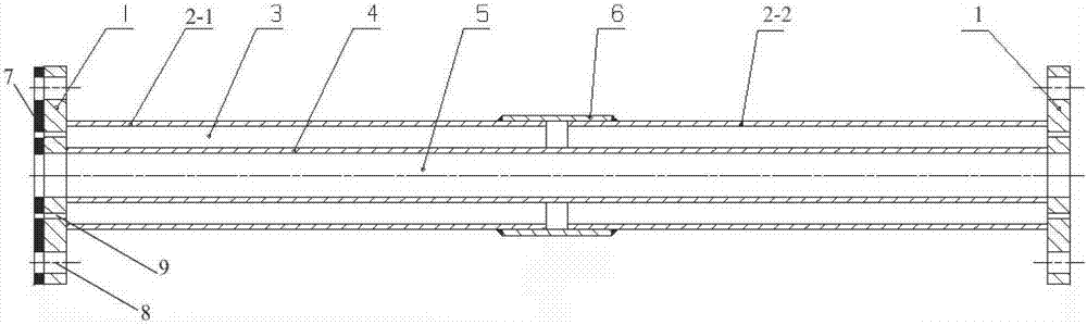
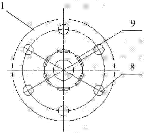
[0020] Such as Figure 1~2 As shown, a double-layer pipe for gas supply to a gas engine includes an inner pipe 4 and an outer pipe 2; it also includes a mounting flange 1, and ventilation holes are distributed between the center circle of the mounting flange 1 and the bolt hole 8 9. The inner tube 4, the outer tube 2 and the mounting flange 1 are made of metal materials. The inner layer pipe 4 is distributed inside the outer layer pipe 2, that is, a gas passage 5 and a ventilation passage 3 are formed; the outer layer pipe 2 is divided into a left section 2-1 and a right section 2-2, and the outer section The outer port of the left section 2-1 of the layer pipe 2 is combined with the left port of the inner layer pipe 4 on one of the mounting flanges 1, and at the same time, the outer port of the right section 2-2 of the outer layer pipe 2 The port and the right port of the inner tube 4 are also combined to the other mounting flange 1; the ventilation holes 9 are distributed b...

specific Embodiment 2

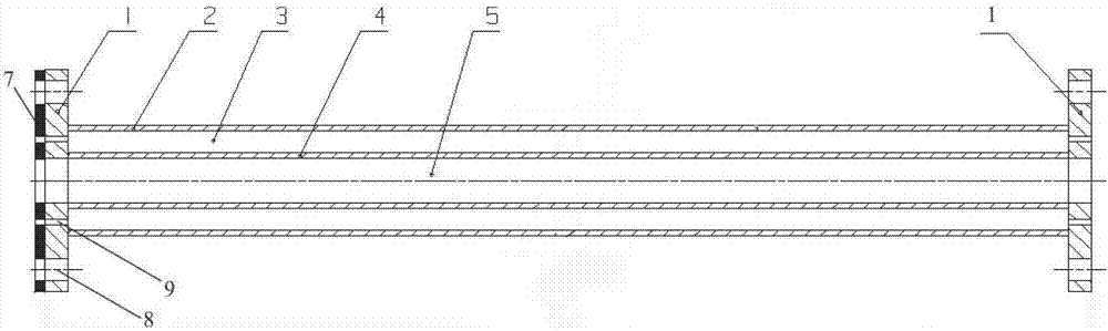
[0022] Such as Figure 3-4 As shown, the difference between this specific embodiment and the above-mentioned specific embodiment 1 is that the outer tube 2 is not segmented, and the length is equivalent to that of the inner tube 4, and the outer diameter of the inner tube 4 is set to match The diameter of the center circle of the mounting flange 1 is welded by inserting the inner tube 4 into the center circle of the mounting flange 1. Of course, the port edge of the inner tube 4 cannot exceed The end face of the mounting flange 1 is used to facilitate the connection of the mounting flange. With this solution, the sleeve 6 can also be omitted. This specific embodiment has a simpler structure and a higher degree of safety.

specific Embodiment 3

[0024] The difference between this specific embodiment and the above specific embodiment 2 is that this specific embodiment adopts 3D printing technology to integrally print the inner layer tube 4, the outer layer tube 2 and the installation flange 1, so , and its constituent materials are not limited to metallic materials, but can also be other non-metallic materials.


PUM


Abstract

The invention discloses a double-layer pipe for gas supply of a gas engine. The double-layer pipe comprises an inner-layer pipe, an outer-layer pipe and an installation flange, wherein air holes are distributed between the center circle of the installation flange and a bolt hole; ports of the inner-layer pipe and the outer-layer pipe are combined on the installation flange; the inner-layer pipe is distributed in the outer-layer pipe; and the air holes are distributed between the wall of the inner-layer pipe and the wall of the outer-layer pipe. The double-layer pipe is very simple and convenient to operate, high in reliability, convenient to disassemble and assemble and easy to repair and replace in the later stage.

Description

technical field [0001] The invention relates to the technical field of gas engine gas supply pipelines, in particular to a double-layer pipeline for gas engine gas supply. [0002] technical background [0003] Gas engines have high requirements for gas intake, and need to have anti-leakage safety measures. Generally, double-layer pipelines are used, that is, the outer layer of the gas needs to be provided with ventilation pipes. When the gas pipe fails and the gas leaks, it can pass through the outer layer. The pipe is exported to the outside of the engine room to prevent the flammable gas from leaking inside the engine room and causing accidents such as explosions; it can be seen that the gas double-layer pipe plays a very important role in the gas engine. At present, the general practice is to weld the inner gas pipeline section by section, and then weld the ventilation pipeline on the outer layer, which needs to be welded on site. Layer pipes are used for destructive mai...

Claims


Application Information

Patent Timeline
Patent Type & Authority Applications(China)
IPC IPC(8): F02M21/02
CPCF02M21/023Y02T10/30
Inventor 覃甲惠
Owner GUANGXI YUCHAI MASCH CO LTD
Why Eureka
Try Eureka