
Integrated test system for battery system

A comprehensive test and battery system technology, applied in the direction of measuring electricity, measuring devices, measuring electrical variables, etc., can solve the problem of high test cost, achieve the effect of reducing test cost, comprehensive test function, and ensuring test test speed and efficiency

Active Publication Date: 2017-09-05
CHINA AVIATION LITHIUM BATTERY LUOYANG
View PDF8 Cites 15 Cited by
  • Summary
  • Abstract
  • Description
  • Claims
  • Application Information

AI Technical Summary

Problems solved by technology

[0006] The purpose of the present invention is to provide a comprehensive test system for the battery system, which is used to solve the problem of high test cost caused by the dynamic test and static test of the battery system respectively

Method used


Image

  • Integrated test system for battery system
  • Integrated test system for battery system
  • Integrated test system for battery system

Examples


Embodiment 1

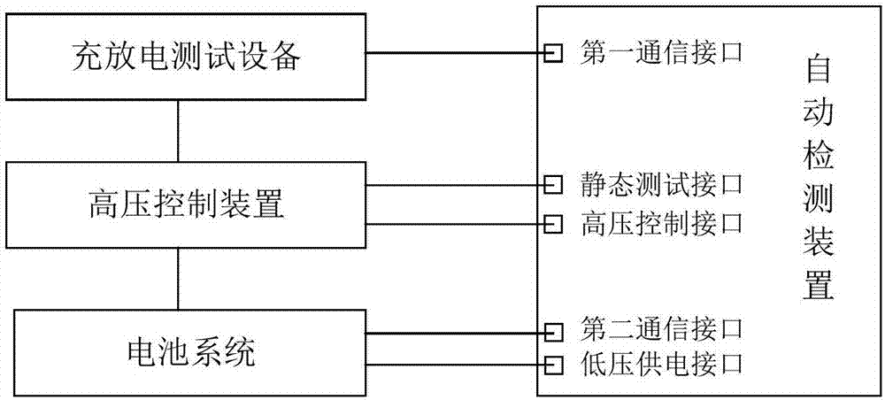
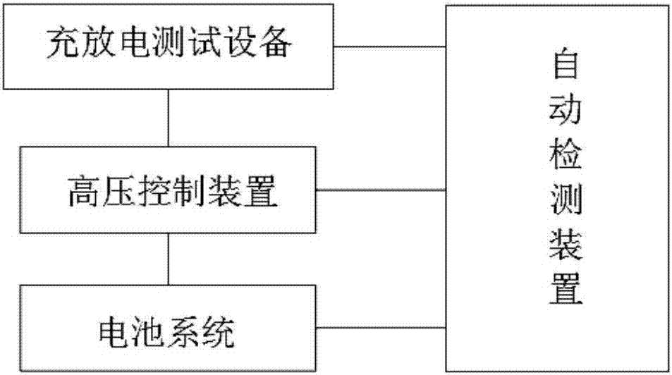
[0026] Such as figure 1 As shown, the comprehensive test system of the present invention includes an automatic detection device, a high-voltage control device and a charge-discharge test device, wherein the high-voltage control device is provided with a static test channel and a dynamic test channel, and the charge-discharge test device is connected to one end of the dynamic test channel. The other end of the test channel is used to connect the battery system.

[0027] The automatic detection device is provided with a static test interface, and is connected to one end of the static test channel through the static test interface, and the other end of the static test channel is used to connect the battery system, and the automatic detection device is connected to the high-voltage control device through the high-voltage control interface for Controlling the on-off of the dynamic test channel and the static test channel, the automatic detection device communicates with the chargin...

Embodiment 2

[0044] Such as figure 2 and Figure 6 As shown, the comprehensive test system includes automatic detection device, high voltage control device, battery system and charge and discharge test equipment.

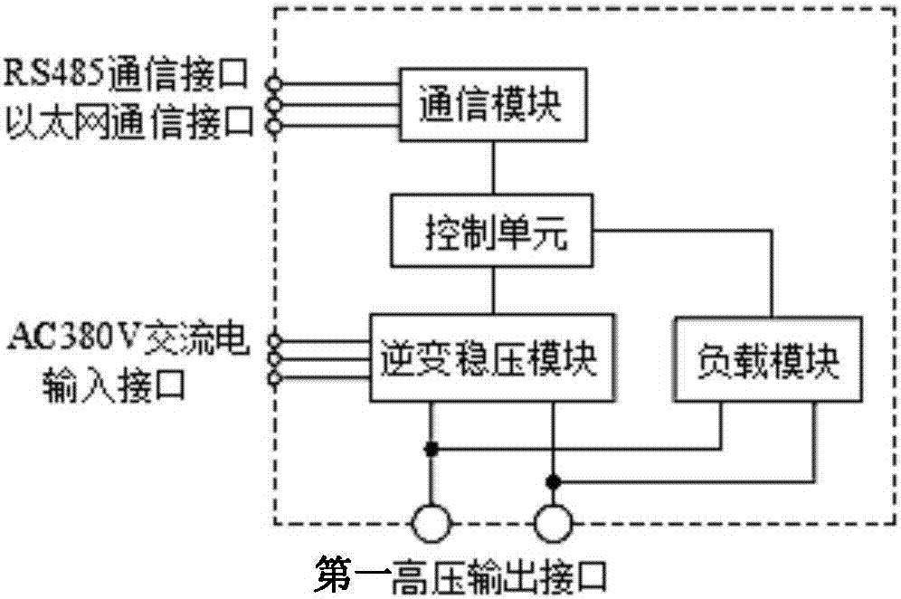
[0045] Among them, the electrical schematic diagram of the charge and discharge test equipment is as follows: image 3 As shown, it includes inverter voltage stabilization module, load module, communication module and charge and discharge control unit. The inverter voltage stabilization module is used to convert the input 380V AC power into a stable high-voltage DC power supply to charge the battery system. The load module is used to discharge the battery system, and the communication module is used to receive external instructions and send them to the charge and discharge control unit. The charge and discharge control unit controls the inverter voltage stabilization module and the load module according to the external instructions received, so as to realize the setting of c...


PUM


Abstract

The invention relates to an integrated test system for a battery system. The integrated test system includes an automatic detection device, a high voltage control device and a charge and discharge test device. The high voltage control device is provided with a static test channel and a dynamic test channel. The static test and dynamic test on the battery system can be realized by the control of one host computer alone, without a change in the test system, through the control of the on and off of the dynamic test channel connected between the charge and discharge device and the battery system and the control of the on and off of the static test channel connected between the automatic test device and the battery system. The comprehensive test functions are gained, and the test cost is greatly reduced while the test speed and efficiency are ensured.

Description

technical field [0001] The invention belongs to the field of battery system testing, and in particular relates to a comprehensive testing system of a battery system. Background technique [0002] In recent years, due to the country's vigorous development of the new energy industry, the development of electric vehicles has advanced by leaps and bounds, and the market share has continued to rise. The continuous expansion of demand for new energy electric vehicles has put forward higher requirements for the delivery capacity of power battery systems. The production mode of mass supply requires fast and complete testing of the power battery system. On the premise of ensuring a comprehensive evaluation of the function and performance of the battery system, the test time should be shortened as much as possible. [0003] The traditional test is a manual test method, requiring operators to use measuring instruments to perform manual measurements. According to the measurement data...

Claims


Application Information

Patent Timeline
Patent Type & Authority Applications(China)
IPC IPC(8): G01R31/36
CPCG01R31/382G01R31/387
Inventor 王东梅温灿国董爱雪李帅
Owner CHINA AVIATION LITHIUM BATTERY LUOYANG
Learn More