Laser radar light path system

An optical path system and lidar technology, applied in radio wave measurement systems, electromagnetic wave re-radiation, and utilization of re-radiation, etc., can solve problems such as large radar measurement blind spots, non-coaxial lidar unable to measure the distance of close-range objects, etc.

Inactive Publication Date: 2017-09-05
LEISHEN INTELLIGENT SYST CO LTD
View PDF6 Cites 26 Cited by
  • Summary
  • Abstract
  • Description
  • Claims
  • Application Information

AI Technical Summary

Problems solved by technology

[0004] The embodiment of the present invention provides an optical path system, which aims to solve the problem in the prior art

Method used


Image

  • Laser radar light path system
  • Laser radar light path system
  • Laser radar light path system

Examples


Embodiment Construction

[0017] In order to make the objectives, technical solutions and advantages of the invention clearer, the following further describes the invention in detail with reference to the accompanying drawings and embodiments. It should be understood that the specific embodiments described here are only used to explain the present invention, but not to limit the present invention.

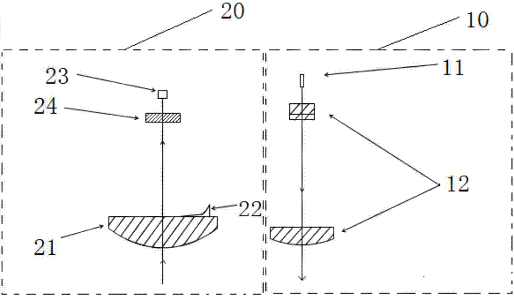
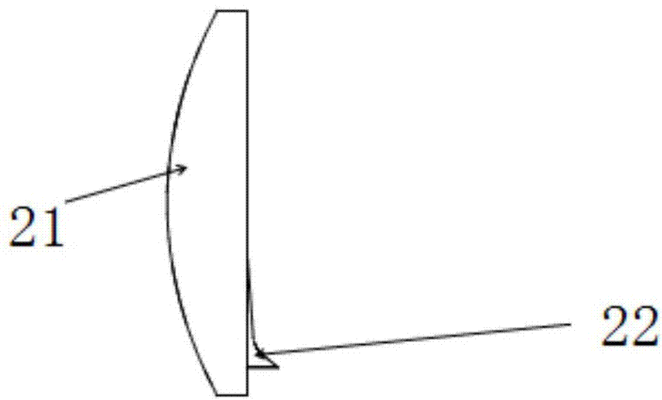
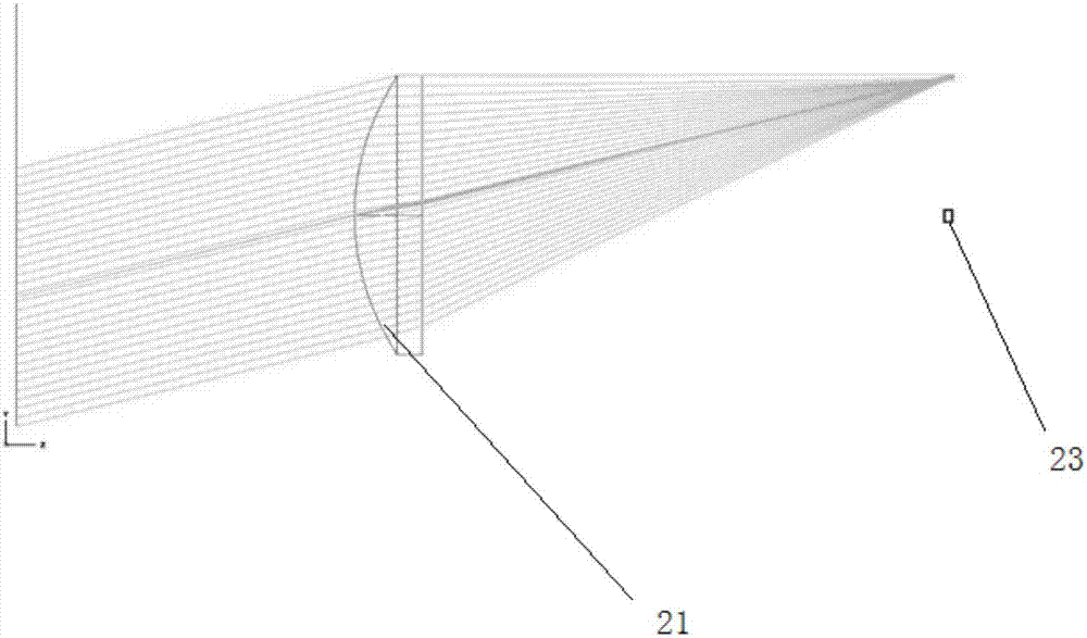
[0018] In the embodiment of the present invention, a laser radar optical system is provided. By setting the laser radar transmitting system, the laser transmitting signal is transmitted to the target object, and by setting a main receiving lens in the receiving system, it is used to reflect the laser light of the target object. The echo signal is focused on the photodetector and is set on the main receiving lens to irradiate the laser echo signal reflected from the target object in the measurement blind area of ​​the main receiving lens to the compensation mirror on the laser detector, and detect it by photoele...


PUM


Abstract

The invention provides a laser radar light path system which is used in the field of laser radar ranging. The system comprises a transmitting system body and a receiving system body. The transmitting system body is used for transmitting laser signals to target objects; the receiving system body is used for receiving laser echo signals reflected from the target objects, and comprises a main receiving lens used for focusing the first laser echo signals reflected from the target objects, a compensating mirror and a photoelectric detector, wherein the compensating mirror is arranged on the main receiving lens and used for compensating the second laser echo signals reflected from the target objects in a measuring blind zone of the main receiving lens, and the photoelectric detector is used for receiving the focused first and second echo signals and outputting corresponding electrical signals so as to obtain distance information of the target objects. Ranging of far objects and ranging of close objects can be achieved at the same time by arranging the compensating mirror on the main receiving lens, the detection range is larger, the detection data is more accurate, and the radar measuring blind zone caused by a non-coaxial optical system can be eliminated.

Description

Technical field [0001] The invention belongs to the field of laser radar ranging, and in particular relates to a laser radar optical path system. Background technique [0002] Lidar is a radar system that emits laser beams to detect target position, speed and other characteristic quantities. It has the advantages of high accuracy, fast operation speed and high efficiency. It is used in the fields of auto driving, robot positioning and navigation, spatial environment mapping, security and security. Essential core sensor. In practical applications, according to different principles, lidar can be divided into: triangle method ranging lidar, time-based pulse ranging lidar, phase method ranging lidar, according to different structures can be divided into coaxial lidar, And non-coaxial lidar. As an example of non-coaxial lidar, the laser signal is emitted to the target object through the transmitting system, and the laser echo signal returned by the target object is received through ...

Claims


Application Information

Patent Timeline
IPC IPC(8): G01S7/483G01S17/08
CPCG01S7/483G01S17/08
Inventor 罗佳林胡小波段佩华
Owner LEISHEN INTELLIGENT SYST CO LTD
Why Eureka
Try Eureka