A voltage equalization circuit of a series battery pack and its working method
A technology of voltage equalization circuit and series battery pack, which is applied in the direction of circuit, secondary battery, secondary battery repair/maintenance, etc. It can solve the problems of energy loss, high cost, and complicated circuit, so as to improve efficiency, reduce volume, and circuit The effect of simple structure
- Summary
- Abstract
- Description
- Claims
- Application Information
AI Technical Summary
Problems solved by technology
Method used
Image
Examples
Embodiment 1
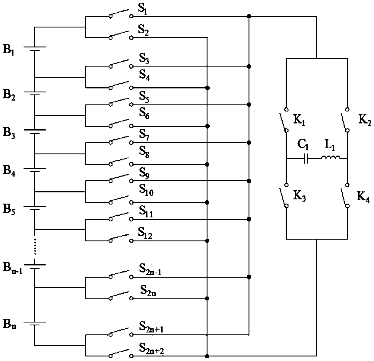
[0026] Such as figure 1 As shown, this embodiment provides a voltage equalization circuit for series-connected battery packs. The voltage equalization circuit includes a battery pack B formed by connecting n battery cells in series. 1 -Bn; 2n+2 balanced controllable switches and 4 charge-discharge switchable controllable switches, the specific circuit connection relationship is as follows figure 1 Shown. Among them, 2n+2 balanced controllable switches are used to connect or disconnect the battery cells or battery packs, and are divided into odd and even groups. The 4 charge-discharge switchable controllable switches are charge-discharge switchable controllable switches K 1 , Charge and discharge switch controllable switch K 2 , Charge and discharge switch controllable switch K 3 And charge and discharge switch controllable switch K 4 , A capacitor C 1 And an inductor L 1 . Among them, battery B 1 -The anode of Bn is connected to two balanced controllable switches, and the cathode...
Embodiment 2
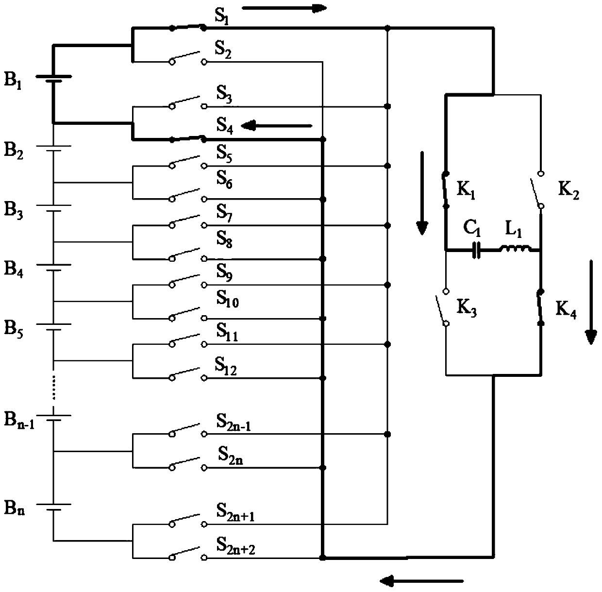
[0030] Such as figure 2 As shown, figure 2 Is the single cell B of the present invention 1 Discharge, capacitor C 1 The energy storage process. When the equalization controller detects that the single battery needs to be discharged, use battery B 1 Discharge to B 2 Take for example. First turn on the balance control switch S 1 , S 4 And charge and discharge switch controllable switch K 1 , K 4 , At this time battery B 1 Via inductor L 1 With capacitor C 1 Connected, under the current limit of the inductor, the battery starts to charge the capacitor.
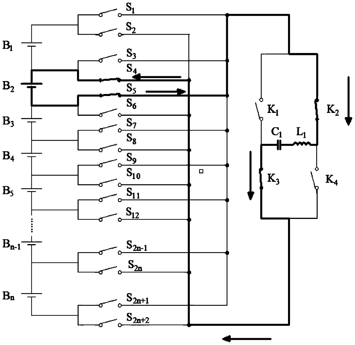
[0031] Such as image 3 As shown, image 3 It is a single battery B 1 After discharge, capacitor C 1 Give battery B after energy storage 2 The process of charging. At this time, turn off the switch during charging and turn on the balance controllable switch S 4 , S 5 And charge and discharge switch controllable switch K 2 , K 3 . At this time, battery B 2 Via inductor L 1 With capacitor C 1 Connection, because the voltage across ...
Embodiment 3
[0033] Such as Figure 4 As shown, Figure 4 Is the multi-cell battery of the present invention (with B 1 , B 2 For example) discharge, capacitor C 1 Energy storage process. Close balance controllable switch S 1 , S 6 And charge and discharge switch controllable switch K 1 , K 4 , Then battery B 1 , B 2 Discharge, the capacitor stores energy. This figure illustrates the discharge process of multiple batteries.
[0034] Such as Figure 5 As shown, Figure 5 Is a multi-cell battery (with B 1 , B 2 For example) after discharge, capacitor C 1 After energy storage, give multiple batteries (with B 3 , B 4 For example) the charging process. Disconnect the switch when charging, open the balance controllable switch S 6 , S 9 And charge and discharge switch controllable switch K 2 , K 3 , The capacitor starts to move towards B 3 , B 4 Recharge. This figure illustrates how the capacitor charges multiple batteries.
PUM
 Abstract
Description
Claims
Application Information
 - R&D
- Intellectual Property
- Life Sciences
- Materials
- Tech Scout
- Unparalleled Data Quality
- Higher Quality Content
- 60% Fewer Hallucinations
Browse by: Latest US Patents, China's latest patents, Technical Efficacy Thesaurus, Application Domain, Technology Topic, Popular Technical Reports.
© 2025 PatSnap. All rights reserved.Legal|Privacy policy|Modern Slavery Act Transparency Statement|Sitemap|About US| Contact US: help@patsnap.com


