Electric vehicle charging gun seal structure

A sealing structure, electric vehicle technology, applied in electric vehicle charging technology, electric vehicles, charging stations, etc., can solve the problems of unreliable connector sealing, short-circuit and leakage accidents, and immature technology, so as to avoid short-circuit and leakage accidents. , The effect of strengthening the sealing effect

Inactive Publication Date: 2017-09-05
山东优安新能源汽车零部件有限公司
View PDF8 Cites 7 Cited by
  • Summary
  • Abstract
  • Description
  • Claims
  • Application Information

AI Technical Summary

Problems solved by technology

[0002] Electric vehicles refer to vehicles powered by vehicle-mounted power supplies and driven by motors to drive wheels, which meet the requirements of road traffic and safety regulations. Due to their smaller impact on the environment than traditional vehicles, their prospects are widely optimistic, but the current technology is not yet mature. , the working process is battery, charging, power conditioner, electric motor, power transmission system, driving the car
[0003] The power part of new energy electric vehicles is mainly composed of battery pack, motor, electric control and external charging pile. The battery pack and charging pile are connected through connectors (charging guns) and wires. Socket main component terminals, socket insulators, socket shells, plug main component terminals. , There is no sealing structure at the joint between the plug terminal and the socket terminal, so it is inevitable that water or other liquids will enter the joint between the plug and the socket during the charging process, causing short circuit and leakage accidents. Therefore, the existing connector (charging gun) is unreliable in sealing during power-on work, and it is easy to cause short circuit and leakage accidents

Method used


Image

  • Electric vehicle charging gun seal structure
  • Electric vehicle charging gun seal structure
  • Electric vehicle charging gun seal structure

Examples


Embodiment Construction

[0021] The present invention will be further described below in conjunction with specific examples. It should be understood that these examples are only used to illustrate the present invention and are not intended to limit the scope of the present invention. In addition, it should be understood that after reading the teachings of the present invention, those skilled in the art can make various changes or modifications to the present invention, and these equivalent forms also fall within the scope defined by the appended claims of the application.

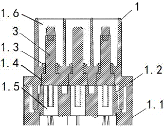
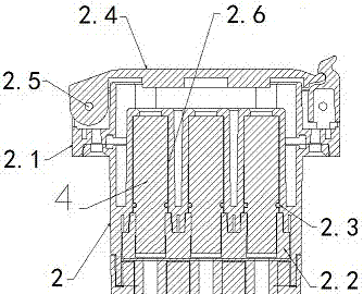
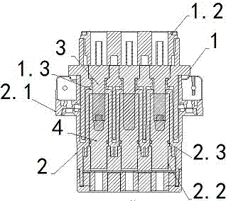
[0022] see Figures 1 to 3 It is a schematic diagram of the structure of the plug, a schematic diagram of the socket, and a schematic diagram of the combined state of the plug and the socket of the present invention, which includes a plug and a socket, and the plug includes a plug insulator 1, a plug shell 1.1, a plug terminal cover 1.2, a plug terminal seal 1.3, and a plug terminal 3 , the socket includes a socket insulator 2, a s...


PUM


Abstract

The invention discloses an electric vehicle charging gun seal structure. A socket seal cover is arranged on the upper portion of a socket shell and is connected with the socket shell through a pin shaft, a socket insulator is arranged at the inner side of the socket shell and fixed through a groove formed in the lower portion of the socket shell in a matched mode, three socket terminal installing grooves are formed in the inner side of the socket insulator, socket terminals are arranged at the inner sides of the three socket terminal installing grooves respectively, socket terminal seal parts are arranged between the three socket terminals and the socket insulator, a socket terminal cover plate is arranged at the inner side of the lower portion of the socket insulator, and the tail ends of the three socket terminals are arranged at the inner side of the socket terminal cover plate. By means of the matching between the socket terminal seal parts and the socket insulator, liquid is prevented from permeating into the inserting connection part, short circuit and electric leakage accidents are avoided, multiple and multi-direction seal between a plug and a socket is achieved by means of seal measures on plug terminals, plug terminal seal parts, a plug insulator and the socket insulator contact face, and the seal effect is enhanced.

Description

technical field [0001] The invention relates to the field of electric vehicles, in particular to a sealing structure for a charging gun of an electric vehicle. Background technique [0002] Electric vehicles refer to vehicles powered by vehicle-mounted power supplies and driven by motors to drive wheels, which meet the requirements of road traffic and safety regulations. Because they have less impact on the environment than traditional vehicles, their prospects are widely optimistic, but the current technology is not yet mature. , The working process is battery, charging, power conditioner, electric motor, power transmission system, and driving the car. [0003] The power part of new energy electric vehicles is mainly composed of battery pack, motor, electric control and external charging pile. The battery pack and charging pile are connected through connectors (charging guns) and wires. Socket main component terminal, socket insulator, socket shell, plug main component ter...

Claims


Application Information

Patent Timeline
Patent Type & Authority Applications(China)
IPC IPC(8): H01R13/52B60L11/18
CPCH01R13/5202H01R13/521B60L53/16Y02T10/70Y02T10/7072Y02T90/14
Inventor 韩宝东李国宾范明辉杨化飞韩兵
Owner 山东优安新能源汽车零部件有限公司
Why Eureka
Try Eureka