
Substation substation group automatic control system and control method

An automatic control system and controller technology, applied in the direction of parallel feeding arrangement of a single network, etc., can solve the problems of large loss of transformers in the station area, very large load rate changes, insufficient power supply capacity of the transformers in the original distribution station area, etc., to improve the operation efficiency. , Improve the safe operation ability, improve the effect of power supply security

Active Publication Date: 2020-08-07
王韶晖
View PDF7 Cites 0 Cited by
  • Summary
  • Abstract
  • Description
  • Claims
  • Application Information

AI Technical Summary

Problems solved by technology

However, the coal-to-electricity plan has led to an increase of 6.9KW in power supply for each household on the basis of the original power supply capacity, which in turn led to insufficient power supply capacity of the transformer in the original station area. The number of transformers in the station area thus increases several times, such as Figure 8 shown
However, this type of new load is a seasonal load. In the three seasons of spring, summer and autumn, the load will return to the original load level. Therefore, the load rate of the transformer in the station area varies greatly in different periods. Most of the time is light load operation, the loss of the transformer in the station area is very large

Method used


Image

  • Substation substation group automatic control system and control method
  • Substation substation group automatic control system and control method
  • Substation substation group automatic control system and control method

Examples


Embodiment Construction

[0044] Embodiments of the present invention are further described below in conjunction with accompanying drawings:

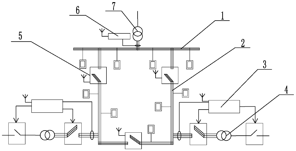
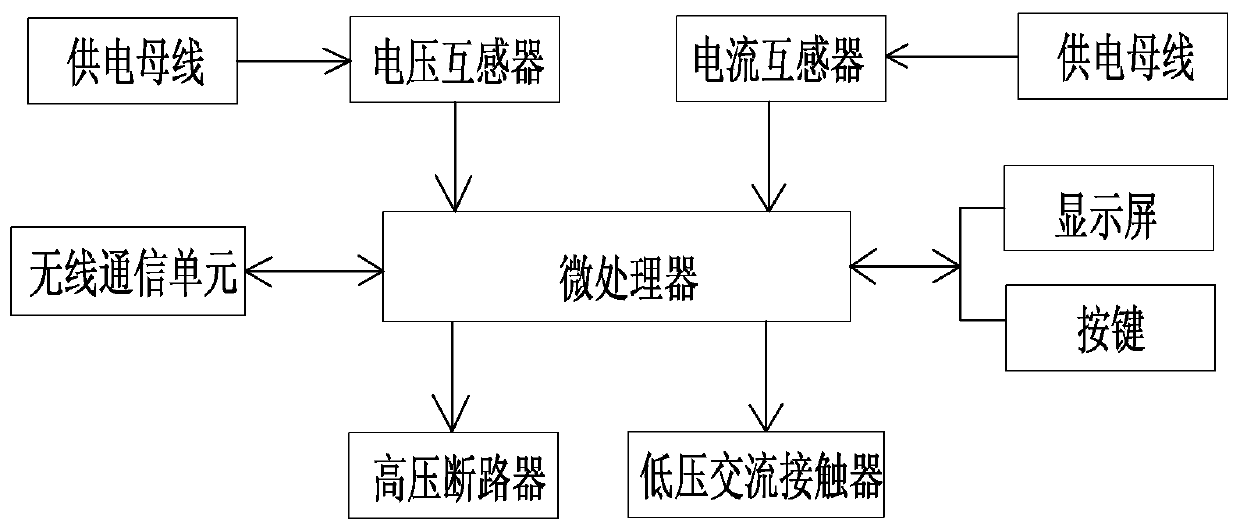
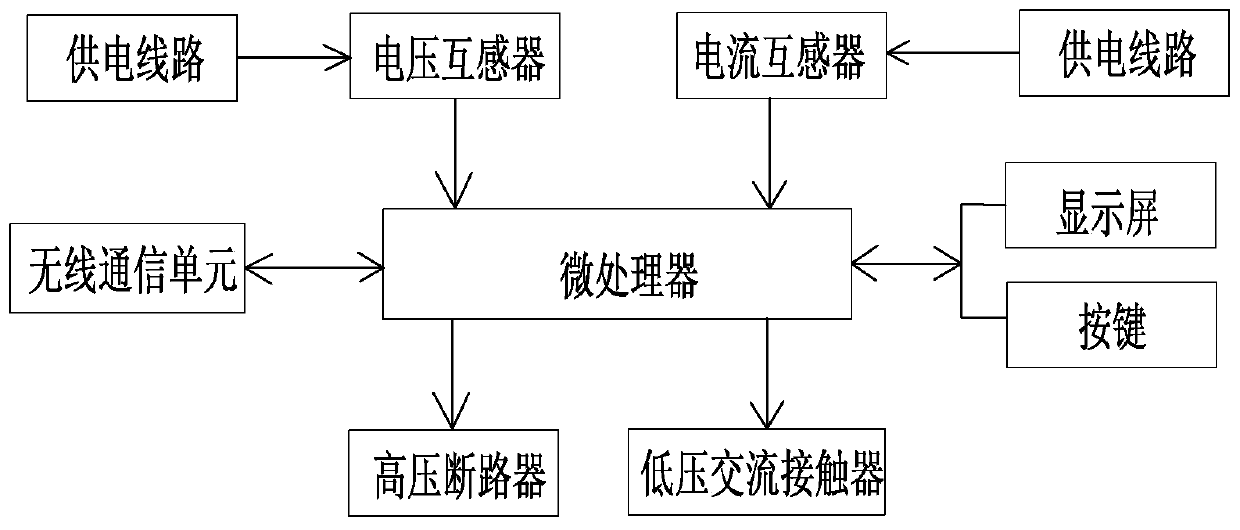
[0045] Such as Figure 1-7 As shown, the station substation group automatic control system of the present invention includes a power supply bus 1 and N sections of power supply lines 2, and the power supply bus 1 and two adjacent sections of power supply lines 2 are connected through a tie switch 5, and the two adjacent sections The power supply lines 2 are connected through a contact switch 5; the power supply bus 1 is provided with a station area main transformer 7, and the station area main transformer 7 side is connected to the station group main controller 6, and the station area transformers are respectively arranged on the power supply line 1 4. The 4 sides of the station area transformer are connected to the station transformer controller 3, and the station transformer controller 3 and the contact switch 5 are connected to the station group master contro...


PUM


Abstract

The invention relates to an automatic control system and a control method for district transformer groups, and belongs to the field of automatic control systems for 10KV / 0.4KV low-voltage distribution networks. The automatic control system comprises power supply bus and N power supply lines. The power supply bus and every two adjacent power supply lines are connected with one another by interconnection switches, and every two adjacent power supply lines are connected with each other by an interconnection switch; a district main transformer is arranged on the power supply bus, a district main transformer side is connected with a district group master controller, district transformers are arranged on the power supply lines, district transformer sides are connected with district transformer controllers, and the district transformer controllers and the interconnection switches are connected with the district group master controller by wireless communication units. The automatic control system and the control method have the advantages that the automatic control system is reasonable in structural design, the numbers of operating district transformers can be regulated and controlled in real time, automatic network reconfiguration can be carried out on distribution networks with the district transformer groups, accordingly, distribution network structures can be optimized, the operation efficiency can be improved, light-load loss can be reduced, and the safe operation capacity of the distribution networks can be improved.

Description

technical field [0001] The invention relates to an automatic control system and a control method for a substation substation group, belonging to the field of automatic control systems for 10KV / 0.4KV low-voltage distribution networks. Background technique [0002] In order to cooperate with the state's instructions on improving the environment and reducing smog, the State Grid has proposed a plan to replace coal with electricity in the rural grid, so that residents in the rural grid will change from burning coal for heating to using electricity for heating. However, the coal-to-electricity plan has led to an increase of 6.9KW in power supply for each household on the basis of the original power supply capacity, which in turn led to insufficient power supply capacity of the transformer in the original station area. The number of transformers in the station area thus increases several times, such as Figure 8 shown. However, this type of new load is a seasonal load. In the thr...

Claims


Application Information

Patent Timeline
Patent Type & Authority Patents(China)
IPC IPC(8): H02J3/38
CPCH02J3/38
Inventor 王韶晖
Owner 王韶晖
Learn More