Electromagnetic lateral edge turning device and method for pipe with preformed hole

A technology of prefabricated holes and side flanging, applied in the field of plastic processing of metal materials, can solve the problems of low energy utilization rate, eddy current drop, affecting the service life of coils, etc. The effect of energy utilization

Active Publication Date: 2017-09-08
HUAZHONG UNIV OF SCI & TECH
View PDF5 Cites 3 Cited by
  • Summary
  • Abstract
  • Description
  • Claims
  • Application Information

AI Technical Summary

Problems solved by technology

However, in practical applications, it is found that after the solenoid coil is closed and switched, the closed eddy current formed along the circumference of the pipe will be cut off by the prefabricated hole structure on the pipe, resulting in a sudden drop in the eddy current.
And most of the radial electromagnetic force formed by the coil is offset by the supporting force of the mold, and the electromagnetic force used for the side flanging of the pipe is very limited
Therefore, the traditional solenoid discharge coil has disadvantages such as low energy utilization rate, insufficient height of the flanged branch pipe and unsatisfactory material bonding effect when the pip...

Method used


Image

  • Electromagnetic lateral edge turning device and method for pipe with preformed hole
  • Electromagnetic lateral edge turning device and method for pipe with preformed hole
  • Electromagnetic lateral edge turning device and method for pipe with preformed hole

Examples


Embodiment Construction

[0033] In order to make the object, technical solution and advantages of the present invention clearer, the present invention will be further described in detail below in conjunction with the accompanying drawings and embodiments. It should be understood that the specific embodiments described here are only used to explain the present invention, not to limit the present invention. In addition, the technical features involved in the various embodiments of the present invention described below can be combined with each other as long as they do not constitute a conflict with each other.

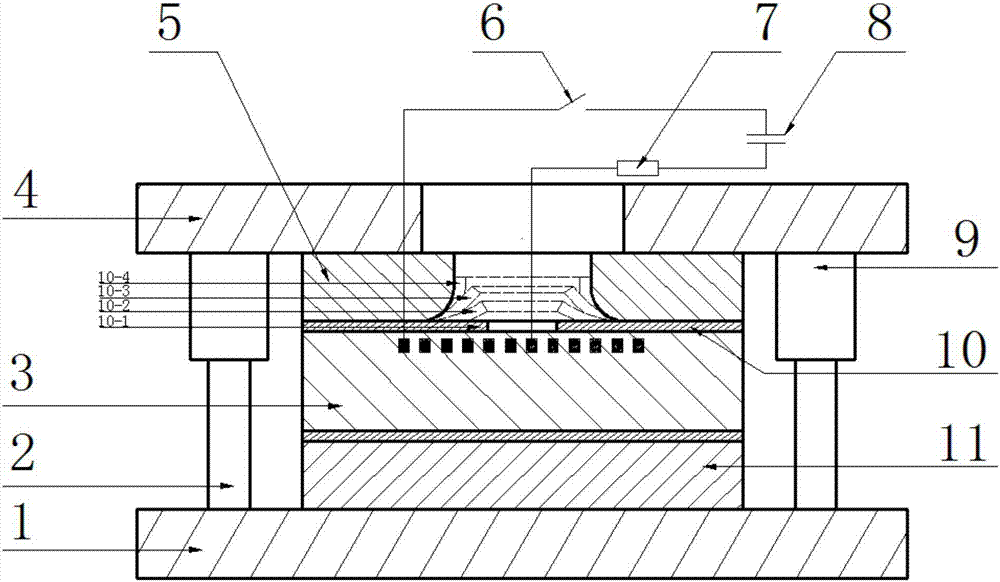
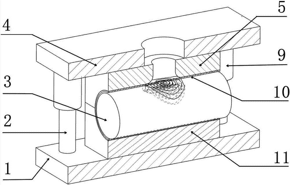
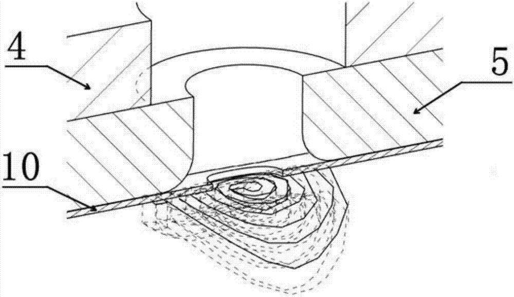
[0034] refer to Figure 1 to Figure 8 , an electromagnetic side flanging device with prefabricated holes, comprising an upper mold frame 4, an upper mold 5, a lower mold 11, a lower mold frame 1, a cylindrical support body 3, a space spiral coil 12 and a pulse discharge circuit, the upper The mold 5 and the lower mold 11 are installed on the upper mold frame 4 and the lower mold frame 1 respect...


PUM


Abstract

The invention belongs to the field of metal material plastic processing and discloses an electromagnetic lateral edge turning device for a pipe with a preformed hole. The device comprises an upper die frame, an upper die, a lower die, a lower die frame, a columnar supporting body, a space spiral coil and a pulse discharge circuit. The upper die is arranged on the upper die frame, the lower die is arranged on the lower die frame, a containing hole is formed by the upper die and the lower die jointly, and the pipe with the preformed hole is sleeved with the columnar supporting body. An edge turning hole is formed in the upper die, the pulse discharge circuit and the space spiral coil are connected to form a pulse magnetic field, the top view of the space spiral coil is spiral, and the side view of the space spiral coil is arc. The space spiral coil is arranged on the top of the columnar supporting body, and a groove for containing the space spiral coil is formed in the top of the columnar supporting body. Radial electromagnetic force generated by the space spiral coil is distributed more intensively in an edge turning hole region, the electromagnetic force is higher, the energy utilization rate is higher, the service life of the coil is longer, and good economic benefits are achieved.

Description

technical field [0001] The invention belongs to the field of plastic processing of metal materials, and more specifically relates to an electromagnetic side flanging device and method for a pipe with prefabricated holes. Background technique [0002] Electromagnetic forming is a forming method that uses electromagnetic force to cause high-speed plastic deformation of metal materials. It has the characteristics of small springback and high forming limit. When forming, the electric energy is converted into high-voltage shock waves in a very short time, which acts on the metal material in the form of pulses, so that the metal material obtains a very high deformation speed instantly, and then undergoes high-speed plastic deformation under the action of inertial force. This technology is mainly used in the fields of aerospace, ships, weapons and automobiles, especially in the plastic processing of pipes, especially the electromagnetic side flanging process of pipes with prefabric...

Claims


Application Information

Patent Timeline
IPC IPC(8): B21D26/14B21D19/00
CPCB21D19/00B21D26/14
Inventor 李建军仇伟黄亮胡微黄攀朱辉
Owner HUAZHONG UNIV OF SCI & TECH
Why Eureka
Try Eureka